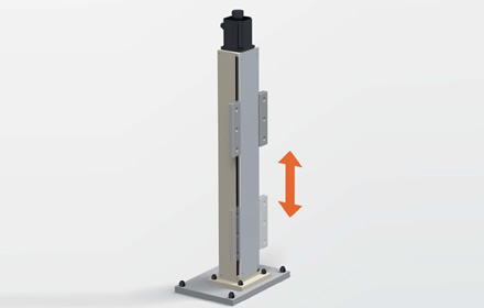
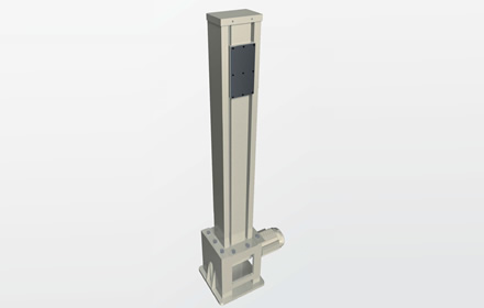
Lift Master Trapezoidal Thread Type
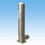
- Cantilever electric lifter using Trapezoidal Screw
- ・Self-locking
Trapezoidal Screw are mathematically self-locking and can be expected to hold loads.
The motor needs a brake mechanism because vibrations and shocks can cause the self-locking mechanism to become ineffective.
Our standard products use brake motors. - Economical
It is more economical than Ball screw type. Taking advantage of the sliding contact Trapezoidal Screw, it is suitable for low speed, low frequency applications.

Features and structure Video content
Benefits
- ・You can freely layout your production line >>Learn more
- ・Easy to use >>More details
- ・Improved working environment >>Learn more
- ・Energy saving effect >>Learn more
Specifications (Trapezoidal Screw type)
- ・Lifting load: 4.90kN to 9.80kN
- ・Stroke: 400mm/1,500mm
- - Drive unit: with three-phase motor
- ・Speed: 0.6-0.9m/min
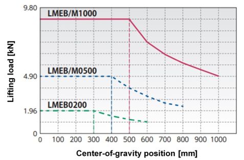
Allowable OHL load curve (based on workpiece mounting surface: see outline drawing)
Catalogs and Instruction Manuals
For a comparison of Zip Chain mechanism and the screw mechanism, please see here.
Model number display
| LME | M | 0500 | S | 10 | G | E |
| | | Lift Master |
| Screw type M: Trapezoidal Screw |
| Lifting load 0500: 4.90kN{500kgf} 1000: 9.80kN {1000kgf} |
| speed S The speed of each model Product model number list Please refer to. |
| stroke 04: 400mm 06: 600mm 08: 800mm 10: 1000mm 12: 1200mm 15: 1500mm |
| Drive unit G: With three-phase motor |
| option See below for details |
Product model number navigation
What type of screws are used?
Lifting load
This is the load that can be raised or lowered at the specified center of gravity.
speed
This symbol indicates the lifting speed.
Please refer to the detailed information for the speed values of each model.
Stroke
The distance that can be raised or lowered.
Drive unit
G: Comes with a three-phase motor.
K: It comes with a servo motor.
Option symbol
J: Bellows are attached to the opening.
L1 to L3: Add one to three position detection sensors.
V: This specifies the power supply voltage will be doubled.
E: A rotary encoder is attached to the rear of the motor.
D1 to D3: Change the motor mounting direction.
D1: 90° rotation from the standard position
D2: 180° rotation from the standard installation position
D3: 270° rotation from the standard mounting position
Product model number list
*Click on the model number to display detailed information.
| Lifting load kN{kgf} |
stroke mm |
Speed S 0.72m/min(50Hz)・0.9m/min(60Hz) |
|---|---|---|
| 4.90 {500} | 400 | LMEM0500S04G |
| 600 | LMEM0500S06G | |
| 800 | LMEM0500S08G | |
| 1000 | LMEM0500S10G | |
| 1200 | LMEM0500S12G | |
| 1500 | LMEM0500S15G | |
| 9.80 {1000} | 400 | LMEM1000S04G |
| 600 | LMEM1000S06G | |
| 800 | LMEM1000S08G | |
| 1000 | LMEM1000S10G | |
| 1200 | LMEM1000S12G | |
| 1500 | LMEM1000S15G |
Option
Front bellows [option code: J]
- Bellows to prevent dust from entering Lift Master from the front.
Supported stroke: 400mm to 1,200mm
*Please contact us if you require bellows mounting for strokes exceeding 1,200 mm.
*Only for LME0200 series and LME0500 series with strokes of 800mm and 1,200mm.
The effective stroke will be shorter when the front bellows is installed. Please contact us for details.
<Installation reference example>
Please contact us for dimensions.

[Click to enlarge]
Add a position detection sensor [option code: L1 to L3]
・The standard model is equipped with four position detection sensors (two for S-speed only),
Up to three sensors are available for S speed only, and one additional sensor is available for other speeds.
・The option symbol is [L1] for adding one sensor, [L2] for adding two sensors, and [L3] for adding three sensors.
If you would like to add more sensors, please contact us.
Compatible model number L1: All standard model numbers
L2, L3: LMEB0200S, LMEM0500S, LMEM1000S only
Motor voltage 400V class [option code: V]
・Change the drive motor voltage to 400V class.
Compatible models: All standard models
With rotary encoder [Option code: E]
- A rotary encoder can be installed on the shaft end of the non-load side of a three-phase motor, enabling the motor rotation signal to be output.
Compatible model: Standard model with three-phase motor
Features
・Controllability
An open collector output signal can be extracted from the reducer, allowing for a variety of operations.
·compact
There is no need to connect the motor shaft and rotary encoder with a coupling.
・Cost reduction
Compared to conventional separate installations, there is no need for couplings, base plates, or leveling work.
Rotary encoder specifications
| Power supply voltage | DC4.5~30V |
|---|---|
| Number of pulses | 100 |
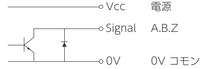
| Output format | Open collector output (NPN type) 6 AB90° phase difference signal +Z origin signal |
| Output Circuit |
|
| Current consumption | 30mA or less |
| Output Voltage | 0.5V or less (At maximum sink current) |
| Maximum sink current | 40mA MAX |
| Signal rising Fall time |
1μs or less |
| Maximum Response Frequency | 240kHz |
| Output circuit withstand voltage | 50V MAX |
| Cable length | 0.5m with connector (Hirose Electric Co., Ltd. DF3-6S-2C) |
| vibration | 4.9m/s 2 {0.5G} or less (20~50Hz) |
Structure and dimensions (rotary encoder mounting part)
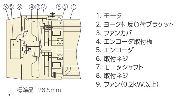
[Click to enlarge]
Wiring Table
| Pin No. | color | connection |
|---|---|---|
| 1 | red | power supply |
| 2 | black | 0V common |
| 3 | blue | Signal A |
| 4 | white | Signal B |
| 5 | yellow | Signal Z |
| 6 | black | shield |
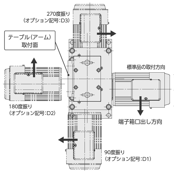
Motor mounting direction change [Option code: D1 to D3]
- The motor installation direction can be changed depending on the installation location of the equipment, the workpiece installation, the transfer direction of the transported items, etc.
*The overall height may change depending on the motor installation direction and stroke.
*The drawings and dimensions below show the specifications for a three-phase motor. Servo motors are also available as an option, so please contact us for details.
Compatible models: All standard models
[Click to enlarge]
D1: Motor installation direction changed by 90 degrees
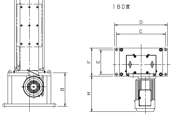
D2: Motor installation direction changed 180 degrees
D3: Motor installation direction changed 270 degrees
| D1: 90 degree offset | D2: 180 degree offset | D3: 270 degree offset |
|---|---|---|
|
[Click to enlarge] |
[Click to enlarge] |
[Click to enlarge] |
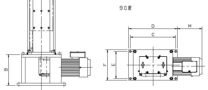

 <D1 Dimension Comparison Table>
| Model | Motor Capacity kW |
Standard motor mounting direction | D1: 90 degree offset | ||||||||||
|---|---|---|---|---|---|---|---|---|---|---|---|---|---|
| B | C | D | E | F | M | B | C | D | E | F | M | ||
| 0200S | 0.1 | - | 250 | 280 | 170 | 200 | 141 | - | 250 | 280 | 170 | 200 | 154 |
| 0200H | 0.4 | 245 | 340 | 370 | 193 | 245 | 340 | 370 | 190 | 220 | 160 | ||
| 0500S | 0.4 | ||||||||||||
| 0500H | 0.75 | 270 | 270 | 210 | 240 | 237 | |||||||
| 0500U | 1.5 | 273 | 400 | 430 | 200 | 230 | 369 | 318 | 400 | 430 | 255 | 285 | 283 |
| 1000S | 0.75 | 250 | 273 | 240 | 270 | 217 | |||||||
| 1000H | 1.5 | 368.5 | 318 | 255 | 285 | 293 | |||||||
| 1000U | 2.2 | 407 | 343 | ||||||||||
<D2 dimension comparison table>
| Model | Motor Capacity kW |
Standard motor mounting direction | D2: 180 degree offset | ||||||||||
|---|---|---|---|---|---|---|---|---|---|---|---|---|---|
| B | C | D | E | F | M | B | C | D | E | F | M | ||
| 0200S | 0.1 | - | 250 | 280 | 170 | 200 | 141 | - | 250 | 280 | 170 | 200 | 172 |
| 0200H | 0.4 | 245 | 340 | 370 | 193 | 245 | 340 | 370 | 223 | ||||
| 0500S | 0.4 | ||||||||||||
| 0500H | 0.75 | 270 | 265 | 300 | |||||||||
| 0500U | 1.5 | 273 | 400 | 430 | 200 | 230 | 369 | 273 | 400 | 430 | 200 | 230 | 366 |
| 1000S | 0.75 | 250 | 290 | ||||||||||
| 1000H | 1.5 | 368.5 | 366 | ||||||||||
| 1000U | 2.2 | 407 | 416 | ||||||||||
<D3 Dimension Comparison Table>
| Model | Motor Capacity kW |
Standard motor mounting direction | D3: 270 degree offset | ||||||||||
|---|---|---|---|---|---|---|---|---|---|---|---|---|---|
| B | C | D | E | F | M | B | C | D | E | F | M | ||
| 0200S | 0.1 | - | 250 | 280 | 170 | 200 | 141 | - | 250 | 280 | 170 | 200 | 80 |
| 0200H | 0.4 | 245 | 340 | 370 | 193 | 245 | 340 | 370 | 190 | 220 | 86 | ||
| 0500S | 0.4 | ||||||||||||
| 0500H | 0.75 | 270 | 270 | 210 | 240 | 163 | |||||||
| 0500U | 1.5 | 273 | 400 | 430 | 200 | 230 | 369 | 318 | 400 | 430 | 255 | 285 | 209 |
| 1000S | 0.75 | 250 | 273 | 240 | 270 | 123 | |||||||
| 1000H | 1.5 | 368.5 | 318 | 255 | 285 | 199 | |||||||
| 1000U | 2.2 | 407 | 249 | ||||||||||
Selection
Our staff will select the lifter that meets your requirements and requirements.
Please click on the "sizing" tab at the top of this page.
Special specification products
Wall mounting specifications
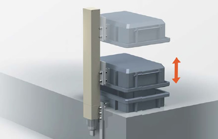
If Lift Master cannot be installed on the floor, it can also be mounted on a wall, making effective use of the sturdy side of the device frame to save space.
Fall prevention specifications
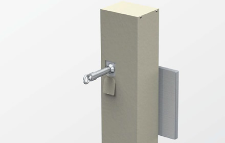
A manual fall prevention pin can be attached to Lift Master to prevent it from falling.
Swivel axis specifications

A manual rotation mechanism is provided at the workpiece mounting section.
Low-profile specification
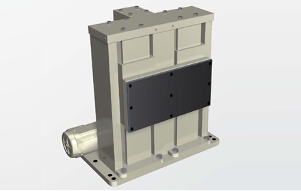
Even if you cannot install Lift Master due to space limitations, we can accommodate you with a reduced height specification.
High-speed specifications
This is a high-speed specification with a maximum speed of 500 mm/s. Please provide a servo motor. Please contact us for details. *High-speed specifications up to 300 mm/sec can be operated with a general-purpose motor using inverter control.
Dustproof and waterproof

Lift Master is dustproof and drip-proof. It can also be used in environments where cutting oil and coolant are present. *Not suitable for outdoor use.
Horizontal Transfer Mechanism
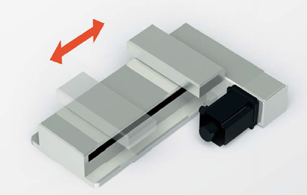
We can also manufacture Lift Master for horizontal transport.
High rigidity specifications
If shaking during lifting or bending when stopped is an issue, we can address this by strengthening the support pillar itself.
Line shaft synchronous type
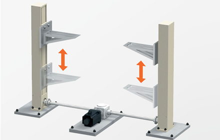
Lift Master can be connected to Tsubaki's ECHT-FLEX coupling and Miter Gear Box to enable synchronized operation. We provide a system that matches your usage conditions, including Gear Motor.
Cable Carrier (CABLEVEYOR) composite proposal
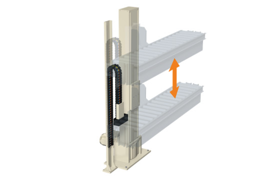
When raising or lowering movable objects such as conveyors, it is possible to consider options such as Cable Carrier (CABLEVEYOR) carriers or frames for Cable Carrier (CABLEVEYOR) to protect the associated cables.

