Shock Guard TGB Series
- A versatile type with a wide range of products and applications
- - Repeated operating torque accuracy is within ±10%.
- -A wide range of sizes are available, and even for the same size, springs are color-coded so that different torque settings can be used.
- - It will Auto reset by simply rotating the drive side.
- -The arrangement of the balls and pockets is a unique combination that only fits together in one place.
- - A non-contact TG sensor detects overload and can stop the motor or issue an alarm (optional).
- -We also have a selection of sprockets and coupling types.
Minimum number of teeth on usable sprockets
・TGB series
| Model number | Minimum number of sprocket teeth | |||||||||||||||||
|---|---|---|---|---|---|---|---|---|---|---|---|---|---|---|---|---|---|---|
| RS40 | RS50 | RS60 | RS80 | RS100 | RS120 | RS140 | RS160 | |||||||||||
| TGB08-L,M,H | 14 | 12 | 13(10) | |||||||||||||||
| TGB12-L,M,H | 16 | 13 | 13(11) | |||||||||||||||
| TGB16-L,M,H | 18 | 15 | 14 | |||||||||||||||
| TGB20-H | 26 | 22 | 19 | 15 | 13 | 13(11) | ||||||||||||
| TGB30-L,H | 32 | 26 | 22 | 18 | 15 | 13 | ||||||||||||
| TGB50-L,M,H | 45(43) | 35 | 30 | 24 | 20 | 17 | ||||||||||||
| TGB70-H | 60(58) | 48(47) | 40 | 32(31) | 26 | 24(22) | ||||||||||||
| TGB90-L,H | 62 | 52 | 40 | 33 | 28 | 25 | 22 | |||||||||||
| TGB110-L,H | 74 | 62 | 48 | 39 | 33 | 29 | 26 | |||||||||||
| TGB130-L,H | 83 | 70 | 53 | 43 | 37 | 32 | 29 | |||||||||||
*The number of teeth in ( ) is not the standard A-type sprocket. If possible, please use a sprocket with a larger number of teeth.
Note: The transmission capacity of the sprocket is not taken into consideration.
Video content
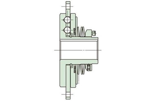
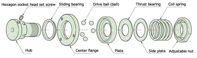
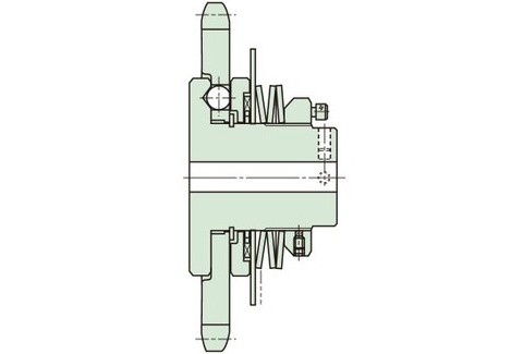
Structure
TGB08~16
TGB20~130
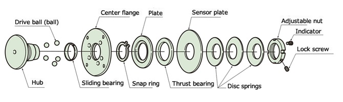
*TGB70 and above have slightly different structures.
Operating principle
Please watch the animation to see the operating principle of the TGB series.
Examples of TGB08-16
During normal operation (engaged)
Torque is transmitted by multiple balls.
The balls are arranged unevenly so there is only one engagement position.
There is no backlash due to the tight meshing of the pressurized ball and pocket, which are held in place without any gaps.
Torque is transmitted from the center flange (pocket) to the ball, then to the hub (pocket) and then to the shaft (or vice versa).
When overloaded (tripped)
When the valve trips due to an overload, the balls come out of the pockets in the center flange and are separated from the plate and center flange.
It moves by sliding between them.
Examples of TGB20-50
During normal operation (engaged)
Torque is transmitted by multiple balls.
The balls are arranged unevenly so there is only one engagement position.
Torque is transmitted from the center flange (pocket) to the ball, then to the hub (pocket) and then to the shaft (or vice versa).
When overloaded (tripped)
When tripped due to overload, the balls come out of their pockets in the hub and roll between the plate and the hub.
All rotating parts during tripping are supported by bearings, so rotation is light and smooth.
*The operating principle of TGB70 to 130 is the same.
Specifications (standard model)
| Set torque range N・m | Repeated operating torque accuracy | Backlash | Reset method |
|---|---|---|---|
| 0.3~7150 | ±10% | Small | Automatic |
Catalogs and Instruction Manuals
Model number display
*Single unit type
| TGB | 30 | - | H | - | TH30JD2 | - | N147 |
| | Series |
| Size |
| | | |
| Shaft hole symbol |
| Torque setting value N・m |
|||
| Spring strength L: Weak spring M: Medium spring H: Strong spring |
|||||||
*Coupling type
| TGB | 50 | - | L | C | - | TH35JD2 | X | CH45ED2 | - | N98 |
| | Series |
| Size |
| | | |
| Coupling type |
| Shock Guard side Shaft hole symbol |
| Coupling side Shaft hole symbol |
| Torque setting value N・m |
||||
| Spring strength | ||||||||||
*With sprocket
| TGB | 50 | - | H | - | 08025 | - | TH50JD2 | - | N294 |
| | Series |
| Size |
| | | |
| Sprocket model number |
| Shaft hole symbol |
| Torque setting value N・m |
||||
| Spring strength | |||||||||
| Shaft hole diameter tolerance | Shaft Hole Diameter | Keyway tolerance | Set screw position | |
|---|---|---|---|---|
| T | H | 35 | J | D2 |
| C | H | 45 | E | D2 |
| T:ショックガード側 C:カップリング側 | F:F7 G:G7 H:H7 J:JS7 P:P7 M:M7 N:N7 K:K7 R:R7 |
Shaft hole diameter is in 1mm increments |
J: New JIS Js9 (standard) P: New JIS P9 F: Old JIS F7 E: Old JIS E9 |
 [Click to enlarge] |
Note) The position of the setscrew on Shock Guard side is the position seen from the adjustment nut side, and the position of the setscrew on the coupling side is the position seen from the hub end face.
■ Tsubaki model No. navigation
Product model number list
*Click on the model number to display detailed information.
| Set torque range N・m |
Single unit | Coupling Type | |||
|---|---|---|---|---|---|
| Shaft hole diameter range mm |
Model number | With sprocket Model number |
Coupling side Shaft hole diameter range mm |
Model number | |
| 0.3~1.4 | 6~8 | TGB08-L | --- | 6~15 | TGB08-LC |
| 0.8~2.1 | TGB08-M | TGB08-MC | |||
| 1.2~2.9 | TGB08-H | TGB08-HC | |||
| 0.7~2.9 | 8~12 | TGB12-L | --- | 8~20 | TGB12-LC |
| 2.0~4.9 | TGB12-M | TGB12-MC | |||
| 3.0~5.8 | TGB12-H | TGB12-HC | |||
| 1.5~4.9 | 9~16 | TGB16-L | --- | 9~25 | TGB16-LC |
| 3.0~7.8 | TGB16-M | TGB16-MC | |||
| 5.9~11 | TGB16-H | TGB16-HC | |||
| 9.8~44 | 10~20 | TGB20-H | TGB20-H-04022
TGB20-H-04027 |
14~42 | TGB20-HC |
| 20~54 | 14~30 | TGB30-L | TGB30-L-06019
TGB30-L-06024 |
20~48 | TGB30-LC |
| 54~167 | TGB30-H | TGB30-H-06019
TGB30-H-06024 |
TGB30-HC | ||
| 69~147 | 24~50 | TGB50-L | TGB50-L-08020
TGB50-L-08025 |
20~55 | TGB50-LC |
| 137~412 | TGB50-M | TGB50-M-08020
TGB50-M-08025 |
TGB50-MC | ||
| 196~539 | TGB50-H | TGB50-H-08020
TGB50-H-08025 |
TGB50-HC | ||
| 294~1080 | 34~70 | TGB70-H | TGB70-H-10022
TGB70-H-10026 |
30~75 | TGB70-HC |
| 441~1320 | 44~90 | TGB90-L | --- | 35~103 | TGB90-LC |
| 931~3140 | TGB90-H | TGB90-HC | |||
| 686~1960 | 54~110 | TGB110-L | --- | 40~113 | TGB110-LC |
| 1570~5100 | TGB110-H | TGB110-HC | |||
| 1180~3040 | 62~130 | TGB130-L | --- | 55~145 | TGB130-LC |
| 2650~7150 | TGB130-H | TGB130-HC | |||
Option
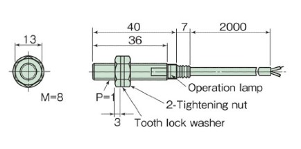
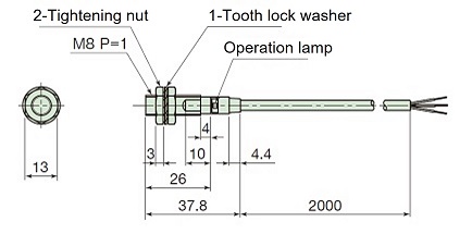
TG sensor
This is a proximity switch type overload detection sensor designed specifically for Shock Guard. It can detect an overload on Shock Guard (movement of the plate in the axial direction) and stop the motor or issue an alarm.
| AC type | DC type | ||
|---|---|---|---|
| Model number | TGS8 | TGS8DN | |
| power supply Voltage |
Rating | AC24~240V | - |
| Usable range | AC20~264V(50/60Hz) | DC10~30V | |
| Current consumption | 1.7mA or less (at AC200V) | 16mA or less | |
| Control output (switching capacity) | 5~100mA | Max 200mA | |
| indicator light | Operation display | ||
| Ambient temperature | -25 to +70°C (but do not freeze) | ||
| Ambient humidity | 35~95% RH | ||
| Output format | - | NPN | |
| Operation form | NC (センサプレートを検知していない時の出力開閉状態を表します) |
||
| Insulation resistance | 50MΩ or more (DC500V megger) between all live parts and case | ||
| mass | Approximately 45g (2m cord length) | Approximately 56g (2m cord length) | |
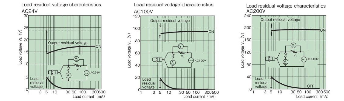
| Residual voltage | >> See characteristic data | 2.0V or less (load current 200mA, cord length 2m) | |
| Instruction Manuals | TG sensor TGS8 | TG sensor TGS8DN | |
Load residual voltage characteristics
Dimensions
AC type TGS8
DC type TGS8DN
Sizing
We will select Shock Guard that best suits your usage conditions from the entire Tsubaki Shock Guard series.
Please click on the "sizing" tab at the top of this page.
For information on selecting and manufacturing drive members (sprockets, etc.), please refer to this link.
Back to top of this pageSpecial specification products
Sprocket integrated type
Upon customer request, we can also accommodate sprocket-integrated types other than standard products. Please select the sprocket and contact us.
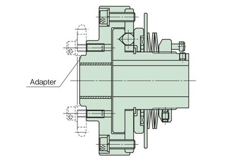
Adapter specifications (A)
This is convenient when using a small diameter sprocket or pulley. When using this product, please specify the specifications of the sprocket or pulley to be installed and contact us.
Forward/reverse type
The trip torque setting can be changed by changing the direction of rotation of Shock Guard. Please contact us for details.