Shock Guard TGK Series

- Multifunctional type with air clutch function
- - By adjusting the air pressure of the regulator, torque can be remotely controlled during operation.
- - You can choose between Type 2, which allows direct installation of A-type sprockets, and Type 5 and Type 7, which combine ECHT-FLEX coupling.
- - The arrangement of the balls and pockets that serve as torque transmission elements is a unique combination that only meshes in one place.
- -It can also be used as an ON-OFF clutch via remote control.
Minimum number of teeth on usable sprockets
・TGK series
| Model number | Minimum number of sprocket teeth | |||||||||||
|---|---|---|---|---|---|---|---|---|---|---|---|---|
| RS35 | RS40 | RS50 | RS60 | RS80 | ||||||||
| TGK20 | 30 | 24 | 20 | 17 | - | |||||||
| TGK30 | 37 | 29 | 24 | 20 | 16 | |||||||
| TGK45 | 50 | 38 | 32 | 27 | 21 | |||||||
Note: The transmission capacity of the sprocket is not taken into consideration.
Structure
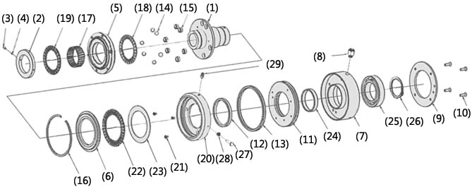
(1) Hub (2) End nut (3) Hexagon socket head set screw (4) Set piece (5) Drive plate (6) Slide plate
(7) Cylinder (8) Pipe joint (9) Cylinder cover (10) Hexagon socket head screw (11) Piston (12) Seal A (13) Seal B
(14) Drive ball (steel ball A) (15) Bush (16) Snap ring A (17) Radial bearing
(18) Thrust bearing A (19) Thrust bearing A (20) Housing (21) Hexagon socket head countersunk screw
(22) Thrust bearing B (23) Thrust race (24) Dry bearing (25) Ball bearing
(26) Snap ring B (27) Sensor target (28) Hexagon nut (29) Grease nipple
Operating principle
Please watch the animation to see the operating principle of the TGK series.
Normal (engaged)
With the TGK series, power enters through the hub and is transmitted to the drive plate on the output side via the drive balls (or vice versa).
Sprockets and Belt Sprockets are attached directly to this drive plate with bolts.
There are holes in the flange of the hub that fit several drive balls, and the drive balls are arranged in these holes.
The output drive plate has a pocket for the drive ball.
When air is sent into the cylinder through the air supply port, the piston moves toward the drive plate.
At this time, the drive balls are pressurized via the slide plate, transmitting power.
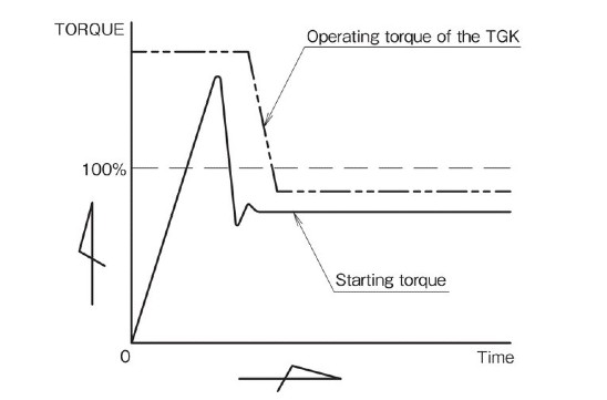
In addition, the torque can be changed to match the load during operation, and a system that switches pressure using a timer or controller can be created to automatically change the torque.
For example, by using this system, it is possible to automatically change between high torque and low operating torque to suit the starting torque, allowing you to set the optimum torque for the machine.
When overloaded (tripped)
When an overload occurs, the drive balls push the slide plate back towards the cylinder against the air pressure, jump out of the pockets in the drive plate, and begin to spin freely.
At this time, the sensor target moves in the direction of the cylinder, and the limit switch detects this movement. The air in the cylinder is released, eliminating the force acting on the drive ball.
Power is completely cut off to protect the machine.
*For examples of limit switch installation, please refer to the product model number page.
Clutch mechanism
When disconnecting the drive system for machine adjustment or maintenance, the air supply is stopped and the air in the cylinder is released. The housing and slide plate are then opened by the spring located inside.
It is pushed back towards the cylinder.
This causes the drive balls to leave the pockets in the drive plate, disengaging the clutch.
The drive plate has a built-in bearing, so it can run idle for long periods without any problems.
Reset method (clutch engagement)
Supply air through the air supply port and restart, and it will automatically return to its original position within one rotation.
The TGK series will continuously reset if rotation continues while air is being supplied after activation, so after an overload occurs, detect the overload with a limit switch or similar and stop the air supply.
Specifications (standard model)
| Set torque range N・m | Repeated operating torque accuracy | Backlash | Reset method |
|---|---|---|---|
| 15~392 | ±5% | Extremely small | Automatic |
■Type 2: A-type sprockets and pulleys can be installed directly.
■Type 5: A coupling type that combines ECHT-FLEX, which allows for angle errors. Parallelism errors are not allowed.
■Type 7: A coupling type that combines ECHT-FLEX, allowing for errors in angle and parallelism.
Catalogs and Instruction Manuals
Model number display
*Single unit type
| TGK | 20 | - | A | 2 | - | TH20JD2 |
| | Series |
| Size |
| | | |
| type 2: Type 2 |
| Shaft hole symbol |
||
| Air Pressure | ||||||
*Coupling type
| TGK | 20 | - | A | 5 | - | TH20JD2 | X | CH30JD2 |
| | Series |
| Size |
| | | | |
| type 5: Type 5 7: Type 7 |
| Shock Guard side Shaft hole symbol |
| Coupling side Shaft hole symbol |
|||
| Air Pressure | ||||||||
| Shaft hole diameter tolerance | Shaft Hole Diameter | Keyway tolerance | Set screw position | |
|---|---|---|---|---|
| T | H | 20 | J | D2 |
| C | H | 30 | J | D2 |
| T:ショックガード側 C:カップリング側 | F:F7 G:G7 H:H7 |
Shaft hole diameter is in 1mm increments |
J: New JIS Js9 (standard) P: New JIS P9 F: Old JIS F7 |
 [Click to enlarge] |
■ Tsubaki model No. navigation
Product model number list
*Click on the model number to display detailed information.
| Set torque range N・m |
Single unit | Coupling Type | |||
|---|---|---|---|---|---|
| Shaft hole diameter range mm |
Model number | Coupling side Shaft hole diameter range mm |
Model number | ||
| Type 2 | Type 5 | Type 7 | |||
| 15~65 | 10~20 | TGK20-A2 | 17~42 | TGK20-A5 | TGK20-A7 |
| 30~147 | 12~30 | TGK30-A2 | 17~60 | TGK30-A5 | TGK30-A7 |
| 90~392 | 22~45 | TGK45-A2 | 27~74 | TGK45-A5 | TGK45-A7 |
Sizing
We will select Shock Guard that best suits your usage conditions from the entire Tsubaki Shock Guard series.
Please click on the "sizing" tab at the top of this page.
Back to top of this pageTorque adjustment
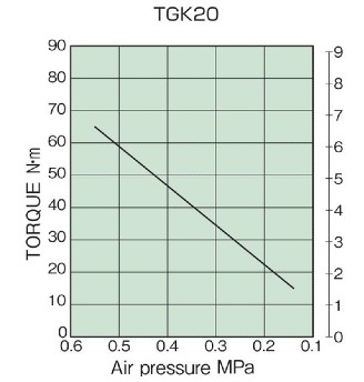
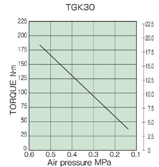
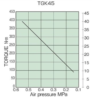
Torque adjustment can be done accurately by referring to the torque correlation diagram, adjusting the air pressure with a regulator (pressure adjuster) to match the required torque, and then sending air into the TGK cylinder.
In addition, the operating torque can be changed by changing the air pressure even while the machine is idling.
Air pressure used: 0.14 to 0.55 MPa
(Note) Make sure that the pressure of the air supply source does not drop below the set pressure.
| Size | Minimum Torque N・m |
Maximum torque N・m |
|||
|---|---|---|---|---|---|
| TGK20 | 15.0 | 65.0 | |||
| TGK30 | 30.0 | 147 | |||
| TGK45 | 90.0 | 392 |
Torque correlation diagram
Air Control System
The TGK series allows you to change the air pressure and operating torque during operation, so you can adjust the starting torque only at start-up.
This allows you to set a higher torque and then change to the optimum torque setting to protect the machine (see the diagram on the right).