Roller chain coupling (wrap type coupling)
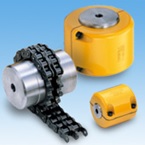
- It consists of a double-strand roller chain and two sprockets.
- The chain is connected by wrapping it around the sprocket and separated by unwinding it, so it can be connected and separated without moving the device.
- ・Applicable shaft diameter: Φ9.5mm to Φ700mm
- Torque range: 99.9 to 717,000 Nm
Features
-
・Excellent durability
The rotational force is shared between the strong roller chain and the surface-hardened sprocket teeth, providing excellent durability.
-
- Easy to connect and disassemble
The roller chain can be easily connected and disassembled by inserting and removing a single joint pin.
-
・Absorbs large misalignments
The clearance between the components accommodates large misalignments on both shafts.
-
・A wide range of models
In addition to the 15 types that comply with JIS standards, 9 other types are standardized, for a total of 24 types (Roller chain coupling JIS B 1456-1989).
Product lineup
| Model number | Maximum shaft bore diameter mm |
Allowable transmission torque N・m |
Model number | Maximum shaft bore diameter mm |
Allowable transmission torque N・m |
|---|---|---|---|---|---|
| CR3812 | Φ16 | 99.9 | CR12018 | Φ125 | 13200 |
| CR4012 | Φ22 | 217 | CR12022 | Φ140 | 17100 |
| CR4014 | Φ28 | 295 | CR16018 | Φ160 | 28600 |
| CR4016 | Φ32 | 386 | CR16022 | Φ200 | 41700 |
| CR5014 | Φ35 | 562 | CR20018 | Φ205 | 57000 |
| CR5016 | Φ40 | 735 | CR20022 | Φ260 | 71900 |
| CR5018 | Φ45 | 931 | CR24022 | Φ310 | 129000 |
| CR6018 | Φ56 | 1750 | CR24026 | Φ380 | 157000 |
| CR6022 | Φ71 | 2370 | CR32022 | Φ430 | 255000 |
| CR8018 | Φ80 | 3880 | CR40020 | Φ470 | 494000 |
| CR8022 | Φ100 | 5580 | CR40024 | Φ590 | 602000 |
| CR10020 | Φ110 | 8780 | CR40028 | Φ700 | 717000 |
*The allowable transmission torque values are for speeds of 50 r/min or less.
Structure
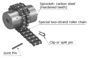
- -The main body consists of two special sprockets with hardened tooth tips and a special two-row roller chain.
- - Joint pins, spring clip or split pins are included as special parts.
*All of these are also sold as individual parts.
Case (sold separately)
Be sure to use the case in the following cases:
- (1) When used at high rotation speeds.
- (2) When used in an abrasive atmosphere such as dusty areas.
- (3) When used in a corrosive atmosphere such as a humid environment.
- - By attaching it to a chain coupling, it prevents lubricant from scattering and dust from entering, extending the life of the coupling.
- - It has a split shape that can be separated perpendicular to the axis, making it convenient for installation and inspection.
Case Structure
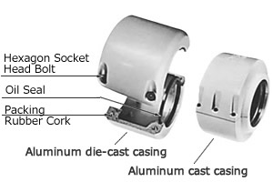
- The case is made of die-cast or cast aluminum and has a two-part structure, to which gaskets (cork with synthetic rubber) are attached.
- - Parts include 4 to 6 hex socket bolts and a dedicated oil seal.
- ・Oil seals and packings are sold as individual parts. Lubricating grease must be purchased separately.
Click here for recommended grease products
- - Install the oil seal on the side with the greatest vibration.
- - When using vertically, the oil seal side should be on the top side.
If you would like to take measures to prevent grease leakage, a quote will be required, so please contact us.
Catalogs and Instruction Manuals
Model number display example
| CR | 38 | 12 | H |
| | Series |
| Chain number |
| Number of sprocket teeth |
| H: Main unit K: Case |
| Fit Bore Series | ||||
| CR6022 | - | NH35JD2 | X | NF40FD2 |
| | Size |
| Left hub symbol |
| Right hub symbol |
||
| Hub Type | Shaft hole diameter tolerance | Shaft Hole Diameter | Keyway tolerance | Set screw position |
|---|---|---|---|---|
| N | H | 35 | J | D2 |
| N | F | 40 | F | D2 |
| N: Standard hub |
F:F7 G:G7 H:H7 J:JS7 P:P7 M:M7 N:N7 K:K7 R:R7 |
Shaft hole diameter is in 1mm increments |
J: New JIS Js9 P: New JIS P9 F: Old JIS F7 E: Old JIS E9 |
 [Click to enlarge] |
Fit Bore Series (Shaft Hole Finish) Product Model Number Navigator
Product model number list
*Click on the model number to display detailed information.
| Main body (pilot bore stock item) | Main body (made to order) | Case | ||
|---|---|---|---|---|
| CR3812H | CR24022H | CR3812K | ||
| CR4012H | CR24026H | CR4012K | ||
| CR4014H | CR32022H | CR4014K | ||
| CR4016H | CR40020H | CR4016K | ||
| CR5014H | CR40024H | CR5014K | ||
| CR5016H | CR40028H | CR5016K | ||
| CR5018H | CR5018K | |||
| CR6018H | CR6018K | |||
| CR6022H | CR6022K | |||
| CR8018H | CR8018K | |||
| CR8022H | CR8022K | |||
| CR10020H | CR10020K | |||
| CR12018H | CR12018K | |||
| CR12022H | CR12022K | |||
| CR16018H | CR16018K | |||
| CR16022H | CR16022K | |||
| CR20018H | CR20018K | |||
| CR20022H | CR20022K |

