Large Conveyor Sprocket Fit bore
- This sprocket is designed specifically for Large size conveyor chain.
- Fit Bore is a finished product with a finished shaft hole.
- You can use it immediately after delivery.
- The processing details are coded, so you can easily order just by entering the model number.

Features
- - The details of shaft hole processing and keyway processing are coded in the product name, so the customer's order details can be communicated accurately.
- - The shaft hole, keyway, tapped hole, etc. are already processed, so the product can be used as is after it arrives to the customer.
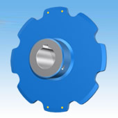
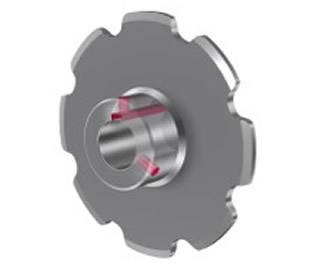
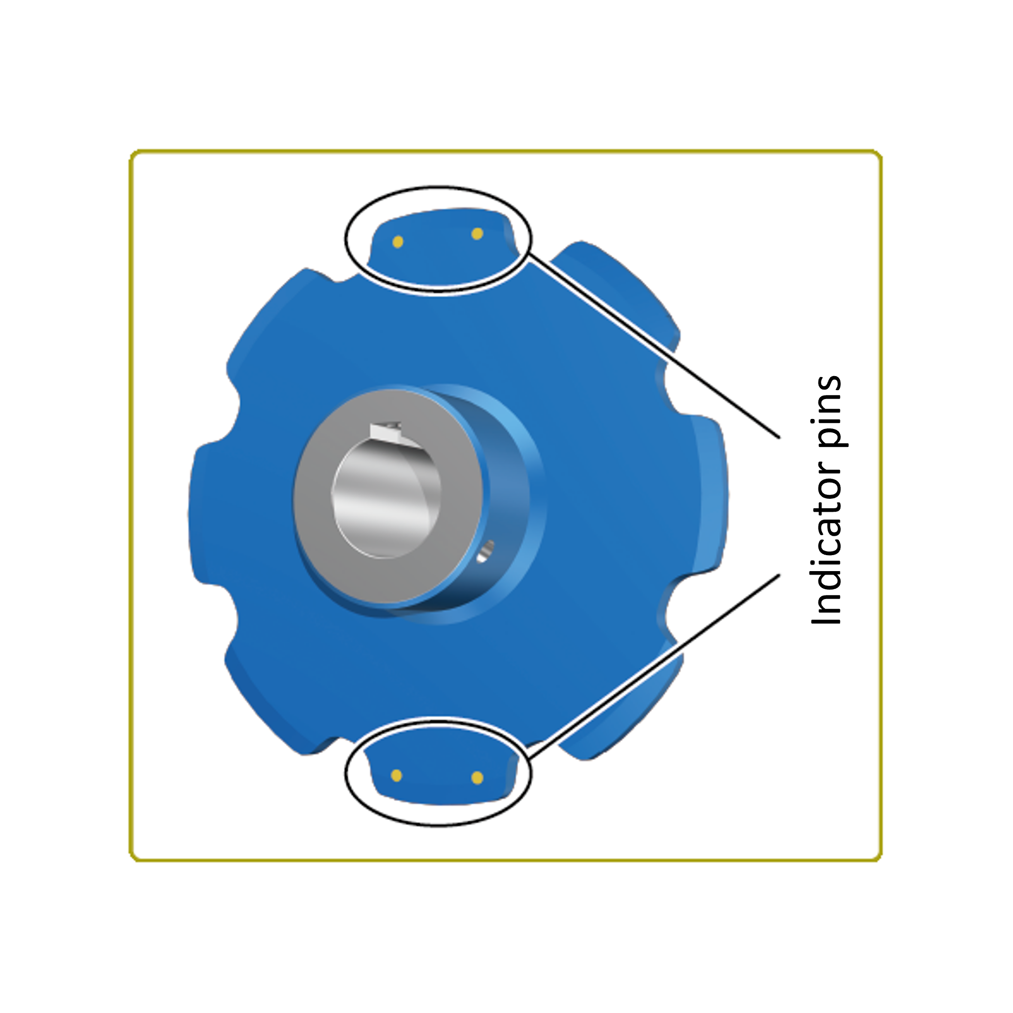
- -You can choose Indicator pins option, which allows you to see at a glance the limit of tooth use.
Catalogs and Instruction Manuals
Model number display example
| RF17200S12T-BW1 | Q | - | H | 090 | N | - | J | 25 | D3 | M16 | - | H1 | - | L2 | -E | |
| | Main unit model number |
| | | | |
| Shaft bore tolerance H:H8 |
| | | | | | | |
| Shaft bore chamfer N: Tsubaki standard A: C1 B: C2 C: C3 |
| | | | |
| Keyway width |
| | | | |
| Tap Size |
| Parallel symbols (2) |
| Paint Code (3) |
| | | | |
|||||
| Tooth tip hardening N: No tooth tip hardening Q: Hardened teeth |
Keyway tolerance W: No keyway J: New JIS Js9 P: New JIS P9 E: Old JIS E9 |
Tap hole machining package (1) |
Indicator pins No markings: None E: Indicator pins |
|||||||||||||
| Shaft Bore Diameter mm |
||||||||||||||||
| (1) Tap hole machining package | (2) Parallel symbols *Set of two | |||||
|---|---|---|---|---|---|---|

*When using H1 and H3 in parallel, the tap arrangement is as follows: |
Hub installation direction image 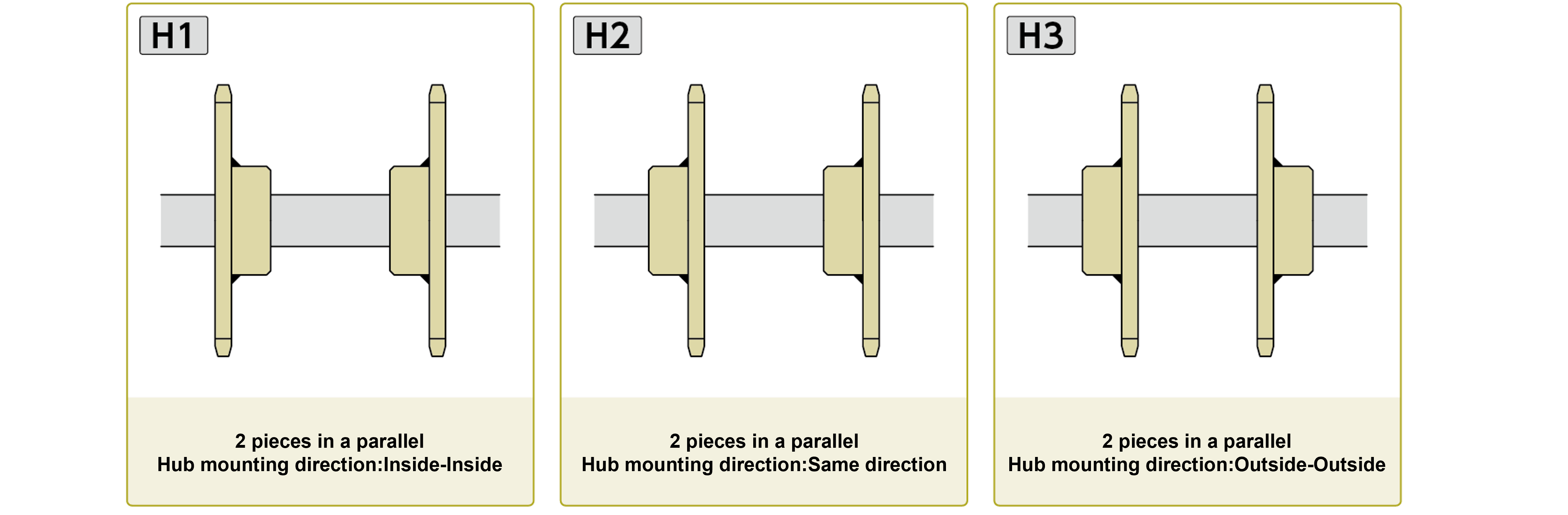
*For H1 and H3, the tap placement will be mirror Image. mirror Image For general sprockets used in parallel, the tap arrangement is machined symmetrically. Example: For D2M16-H1-L0 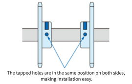
|
|||||
| (3) Paint code | ||||||

|
Product List
Metric pitch
| Model number | R Roller | F Roller | S Roller | |||||||||
|---|---|---|---|---|---|---|---|---|---|---|---|---|
| Number of teeth | Number of teeth | Number of teeth | ||||||||||
| 6 | 8 | 10 | 12 | 6 | 8 | 10 | 12 | 6 | 8 | 10 | 12 | |
| RF03075 | ● | ● | ● | ● | ● | ● | ● | ● | ● | ● | ● | ● |
| RF03100 | ● | ● | ● | ● | ● | ● | ● | ● | ● | ● | ● | ● |
| RF05075 | - | - | - | - | - | - | - | - | - | ● | ● | ● |
| RF05100 | ● | ● | ● | ● | ● | ● | ● | ● | ● | ● | ● | ● |
| RF05125 | ● | ● | ● | ● | ● | ● | ● | ● | ● | ● | ● | ● |
| RF05150 | ● | ● | ● | ● | ● | ● | ● | ● | ● | ● | ● | ● |
| RF08125 | ● | ● | ● | ● | ● | ● | ● | ● | ● | ● | ● | ● |
| RF08150 | ● | ● | ● | ● | ● | ● | ● | ● | ● | ● | ● | ● |
| RF10100 | ● | ● | ● | ● | - | - | - | - | ● | ● | ● | ● |
| RF10125 | ● | ● | ● | ● | ● | ● | ● | ● | ● | ● | ● | ● |
| RF10150 | ● | ● | ● | ● | ● | ● | ● | ● | ● | ● | ● | ● |
| RF12200 | ● | ● | ● | ● | ● | ● | ● | ● | ● | ● | ● | ● |
| RF12250 | ● | ● | ● | ● | ● | ● | ● | ● | ● | ● | ● | ● |
| RF17200 | ● | ● | ● | ● | ● | ● | ● | ● | ● | ● | ● | ● |
| RF17250 | ● | ● | ● | ● | ● | ● | ● | ● | ● | ● | ● | ● |
| RF17300 | ● | ● | ● | ● | ● | ● | ● | ● | ● | ● | ● | ● |
Inch pitch
| Model number | R Roller | F Roller | S Roller | |||||||||
|---|---|---|---|---|---|---|---|---|---|---|---|---|
| Number of teeth | Number of teeth | Number of teeth | ||||||||||
| 6 | 8 | 10 | 12 | 6 | 8 | 10 | 12 | 6 | 8 | 10 | 12 | |
| RF430 | ● | ● | ● | ● | - | - | - | - | ● | ● | ● | ● |
| RF204 | - | - | - | - | - | - | - | - | - | ● | ● | ● |
| RF450 | ● | ● | ● | ● | ● | ● | ● | ● | ● | ● | ● | ● |
| RF650 | ● | ● | ● | ● | ● | ● | ● | ● | ● | ● | ● | ● |
| RF214 | ● | ● | ● | ● | - | - | - | - | ● | ● | ● | ● |
| RF205 | - | - | - | - | - | - | - | - | - | ● | ● | ● |
| RF6205 | ● | ● | ● | ● | ● | ● | ● | ● | ● | ● | ● | ● |
| RF212 | ● | ● | ● | ● | - | - | - | - | ● | ● | ● | ● |
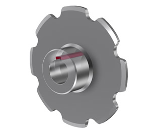
Machining contents
*Click to display detailed information.
| Shaft hole processing (L) | Keyway processing (K) | Tap hole processing (D) |
|---|---|---|
 |
 |
 |
|
・Processing dimensions are integers in 1mm increments only ・Processing tolerance: H8 only |
・Parallel keyway only ・Processing tolerance...selectable |
・Processing size can be selected ・You can select up to two processing locations -Hex socket set screw included (recessed tip) |
 Shaft hole machining dimensions list
In the case of JS9/P9 (new JIS)
| Applicable shaft hole diameter (mm) |
Keyway width (mm) |
Tap Size (Tsubaki standard) |
Selected size |
|---|---|---|---|
| 19~22 | 6 | M6 | M5 |
| 22~30 | 8 | M6 | M5, M8 |
| 30~38 | 10 | M8 | M6, M10 |
| 38~44 | 12 | M8 | M6, M10 |
| 44~50 | 14 | M8 | M6, M10 |
| 50~58 | 16 | M10 | M8, M12 |
| 58~65 | 18 | M10 | M8, M12 |
| 65~75 | 20 | M12 | M10, M16 |
| 75~85 | 22 | M12 | M10, M16 |
| 85~95 | 25 | M16 | M12, M20 |
| 95~110 | 28 | M16 | M12, M20 |
| 110~130 | 32 | M20 | M16 |
| 130~150 | 36 | M20 | M16 |
| 150~170 | 40 | M20 | M16 |
| 170~175 | 45 | M24 | M20 |
In the case of E9 (old JIS)
| Applicable shaft hole diameter (mm) |
Keyway width (mm) |
Tap Size Tsubaki Standard |
Selected size |
|---|---|---|---|
| 19~20 | 5 | M5 | M4 |
| 21~30 | 7 | M6 | M5 |
| 31~40 | 10 | M8 | M6, M10 |
| 41~50 | 12 | M8 | M6, M10 |
| 51~60 | 15 | M8 | M6, M10 |
| 61~70 | 18 | M10 | M8, M12 |
| 71~80 | 20 | M12 | M10, M16 |
| 81~95 | 24 | M12 | M10, M16 |
| 96~110 | 28 | M16 | M12, M20 |
| 111~125 | 32 | M20 | M16 |
| 126~140 | 35 | M20 | M16 |
| 141~160 | 38 | M20 | M16 |
| 161~175 | 42 | M20 | M16 |
Tsubaki standard shaft hole chamfer
| Applicable shaft hole diameter (mm) | Chamfer |
|---|---|
| ~50 | C0.6 |
| 51~80 | C1 |
| 81~120 | C1.6 |
| 121~175 | C2 |
| Shaft Hole Diameter | Selectable chamfer amount | |||
|---|---|---|---|---|
| ~44 | N | A | B | - |
| 45~ | N | A | B | C |
| H0 | None |
| H1 | Hub installation direction: Inner-inner |
| H2 | Hub installation direction: Same direction |
| H3 | Hub mounting direction: Outer-outer |
- - For parallel use, when two sprockets are used on the same axis, the keyway position is aligned in the specified installation direction.
- - Please select the hub mounting direction from the three patterns shown in the diagram below.
Hub installation direction image
| L0 | No paint (rust prevention oil applied) |
| L1 | Lacquer paint (standard paint color) |
| L2 | Lacquer paint (Indicator pins paint color) |
・If Indicator pins specification is painted, L2 will be blue.
| E | Indicator pins |
| Anonymous | None |
- - Brass pin embedded specification.
- - Embed into two teeth on each side of the sprocket tooth section, aiming for 0 degrees and 180 degrees.
If keyway processing is available, one is embedded in the tooth above the keyway
Other
| Limitations | Please contact us for inspection report and material certificate. (If submission is required, it will be treated as a general special form.) |
|---|

