Linipower Jack JWB (ball screw type)
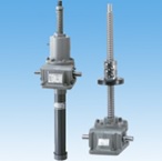
- The JWB (Ball screw type) is a high-performance screw jack suitable for medium speed applications.
- The main components are precision Ball screw and high-precision worm gears.
- Designed for medium speed applications, the use of Ball screw provides high efficiency and a long life.
Features
-
-High efficiency
Ball screw provides high efficiency and produces a large thrust with a small drive source.
-
・Higher speeds
Compared to Trapezoidal Screw types, the increased efficiency of the screw allows for smoother operation at higher speeds.
-
・Long lifespan
Highly reliable Ball screw are used, allowing for predictable running life and ensuring a long service life.
*It does not have a self-locking mechanism, so a brake is required.
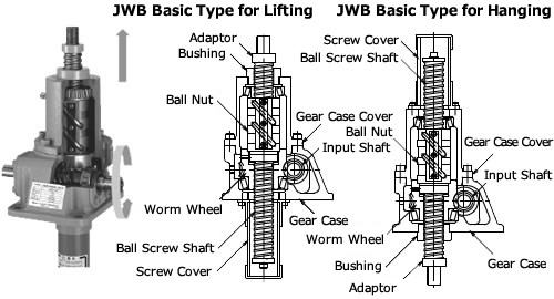
Basic specification structure
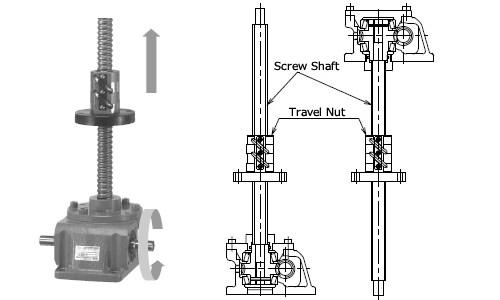
Traveling nut structure
Standard model list
・Basic capacity
| Frame No. | Basic capacity kN {tf} | Worm reduction ratio | |
|---|---|---|---|
| H | L | ||
| 005 | 4.90 {0.5} | 5 | 20 |
| 010 | 9.80 {1} | 5 | 20 |
| 025 | 24.5 {2.5} | 6 | 24 |
| 050 | 49.0 {5} | 6 | 24 |
| 100 | 98.0 {10} | 8 | 24 |
| 150 | 147 {15} | 8 | 24 |
| 200 | 196 {20} | 8 | 24 |
| 300 | 294 {30} | 10 2/3 | 32 |
| 500 | 490 {50} | 10 2/3 | 32 |
| 750 | 735 {75} | 10 2/3 | 32 |
| 1000 | 980 {100} | 12 | 30 |
·Stroke
| Frame No. | 5 | 10 | 25 | 50 | 100 | 150 | 200 | 300 | 500 | 750 | 1000 |
|---|---|---|---|---|---|---|---|---|---|---|---|
| 100 | ○ | ○ | ○ | ○ | ○ | ○ | ○ | △ | △ | △ | △ |
| 200 | ○ | ○ | ○ | ○ | ○ | ○ | ○ | △ | △ | △ | △ |
| 300 | ○ | ○ | ○ | ○ | ○ | ○ | ○ | △ | △ | △ | △ |
| 400 | ○ | ○ | ○ | ○ | ○ | ○ | ○ | △ | △ | △ | △ |
| 500 | ○ | ○ | ○ | ○ | ○ | ○ | ○ | △ | △ | △ | △ |
| 600 | ○ | ○ | ○ | ○ | ○ | ○ | ○ | △ | △ | △ | △ |
| 800 | ○ | ○ | ○ | ○ | ○ | ○ | ○ | △ | △ | △ | △ |
| 1000 | △ | ○ | ○ | ○ | ○ | ○ | ○ | △ | △ | △ | △ |
| 1200 | - | △ | ○ | ○ | ○ | ○ | ○ | △ | △ | △ | △ |
| 1500 | - | - | △ | ○ | ○ | ○ | ○ | △ | △ | △ | △ |
| 2000 | - | - | - | △ | △ | △ | ○ | △ | △ | △ | △ |
- ○: Standard product, △: Made to order, - marks are manufactured according to the conditions of use. Please contact us for details.
- Traveling nut specifications for frame numbers JWB300 and above will be manufactured on a case-by-case basis.
- *Confirmation of usage conditions is required for production of JWB750 and 1000 types.
Catalogs and Instruction Manuals
Model number display example
| JW | B | 050 | U | S | H | 10 | U |
| | Series Name Linipower jack |
| | | | | | | | | | | | |
| Basic capacity 005: 4.90kN{0.5tf} 010: 9.80kN{1tf} 025: 24.5kN{2.5tf} 050: 49.0kN{5tf} 100: 98.0kN{10tf} 150: 147kN{15tf} 200: 196kN{20tf} |
| | | | | | | | | | | | |
| | | | | | | |
| Worm reduction ratio L, H For the actual reduction ratio, please refer to the detailed information. |
| Nominal stroke 1: 100mm 2: 200mm 3: 300mm 4: 400mm 5: 500mm 6: 600mm 8: 800mm 10: 1000mm 12: 1200mm 15: 1500mm 20: 2000mm |
| Flange mounting direction *Notation required only for traveling nut specifications. |
| Screw specifications S: Basic form M: Anti-rotation specification R: Traveling nut specification |
|||||||
| Screw Type B: Ball screw |
Mounting Shape U: For pushing up D: For hanging |
||||||
■ Tsubaki model No. navigation
Screw Type
M: Trapezoidal Screw type.
B: Ball screw type.
H: High lead Ball screw type.
Basic capacity
This is the basic capacity that the jack body can handle.
Mounting Shape
U: This type has a screw shaft on the opposite side of the main body mounting base.
D: This type has a screw shaft protruding from the main body mounting base side.
Screw specifications
S: This is the basic form in which the screw shaft moves.
M: The basic form in which the screw shaft moves.
The screw shaft has an anti-rotation function.
R: The screw shaft rotates and the nut moves.
Worm reduction ratio
Reduction ratio of the worm reducer.
Please refer to the detailed information for the reduction ratio values of each model.
Stroke
travel distance of the threaded shaft or traveling nut.
Flange mounting direction
For traveling nut types, specify which side of the nut the mounting flange should be on.
U: Upper side
D: Lower side
Option symbol
J: It comes with bellows.
B: Comes with End fitting of the rod.
I: Equipped with I-type end fitting.
M: Comes with table-shaped End fitting.
C: Equipped with clevis.
Y: A limit switch with a mechanical counter.
K2: Two built-in microswitches detect the stroke position.
K4: Equipped with four built-in microswitches that detect the stroke position.
P: Equipped with a potentiometer that detects the stroke position.
R: Equipped with a rotary encoder that outputs a stroke movement signal.
E: Comes with a three-phase brake motor.
The power supply supports 200/200/220V 50/60/60Hz.
EV: Comes with a three-phase motor with brake.
The power supply supports 400/400/440V 50/60/60Hz.
G1: Equipped with a three-phase gear motor with brake, the reduction ratio is 1/5.
The power supply supports 200/200/220V 50/60/60Hz.
G2: Equipped with a three-phase gear motor with brake, the reduction ratio is 1/10.
The power supply supports 200/200/220V 50/60/60Hz.
Product model number list
*Click on the model number to display detailed information. Open all Close all
 Basic capacity frame number "005" 4.90kN {0.5tf} (Model number JWB005~)
Basic capacity frame number "010" 9.80kN {1tf} (model number JWB010~)
Basic capacity frame number "025" 24.5kN {2.5tf} (model number JWB025~)
Basic capacity frame number "050" 49.0kN {5tf} (model number JWB050~)
Basic capacity frame number "100" 98.0kN {10tf} (Model number JWB100~)
Basic capacity frame number "150" 147kN {15tf} (model number JWB150~)
Basic capacity frame number "200" 196kN {20tf} (model number JWB200~)
Special support
・Special support is available to suit your usage conditions.

