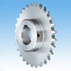
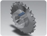
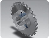
Double Double pitch Sprocket Fit bore Bore
- We process the shaft hole, keyway, and tapped hole before shipping.
- There is no need for the customer to perform any additional work, and the product can be used as is.
- You can freely select from the processing options you have set.

Features
- - The details of shaft hole processing and keyway processing are coded in the product name, so the customer's order details can be communicated accurately.
- ・ Fit Bore Drawing Library allows customers to check the details of their orders in advance using drawings. (See the banner above.)
- - The shaft hole, keyway, tapped hole, etc. are already processed, so the product can be used as is after it arrives to the customer.
Note: When selecting sprocket specifications
- You must select a sprocket that is compatible with your operating environment and the chain specifications you are using. For details, please refer to the compatibility chart for various chains and sprockets.
If you require bearing hole processing, please click here. If you require materials other than steel or stainless steel or surface treatment, etc., these will be special orders, so please contact us here.Catalogs and Instruction Manuals
Model number display example
| Double pitch sprocket | |||||||||||||
| RF2060S-1B1100T | Q | - | H | 030 | N | - | J | 08 | D2 | M06 | - | H1 | -K |
| | Main unit model number |
| | | |
| | | |
| Shaft Hole Diameter mm |
| | | | | |
| | | |
| Keyway width mm |
| | | |
| Tap Size |
| Parallel symbols (5) |
| Surface Treatment (6) |
|||
| Tooth tip hardening None: No tooth tip hardening Q: Hardened teeth |
Shaft bore tolerance (1) |
Keyway Tolerance (3) |
Tap hole machining package (4) |
||||||||||
| Shaft bore chamfer (2) |
|||||||||||||
| (1) Shaft bore tolerance | (2) Shaft bore chamfer | (3) Keyway tolerance | (4) Tap hole machining package |
|---|---|---|---|
|
H:H7 G:G7 M:M7 |
N: Tsubaki standard A: C1 B: C2 C: C3 |
W: None J: New JIS Js9 P: New JIS P9 F: Old JIS F7 E: Old JIS E9 |

*When using H1 and H3 in parallel, the tap arrangement is as follows: |
| (5) Parallel symbols *Set of two | (6) Surface treatment |
|---|---|
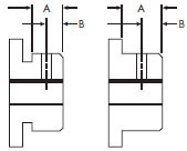
Hub installation direction image 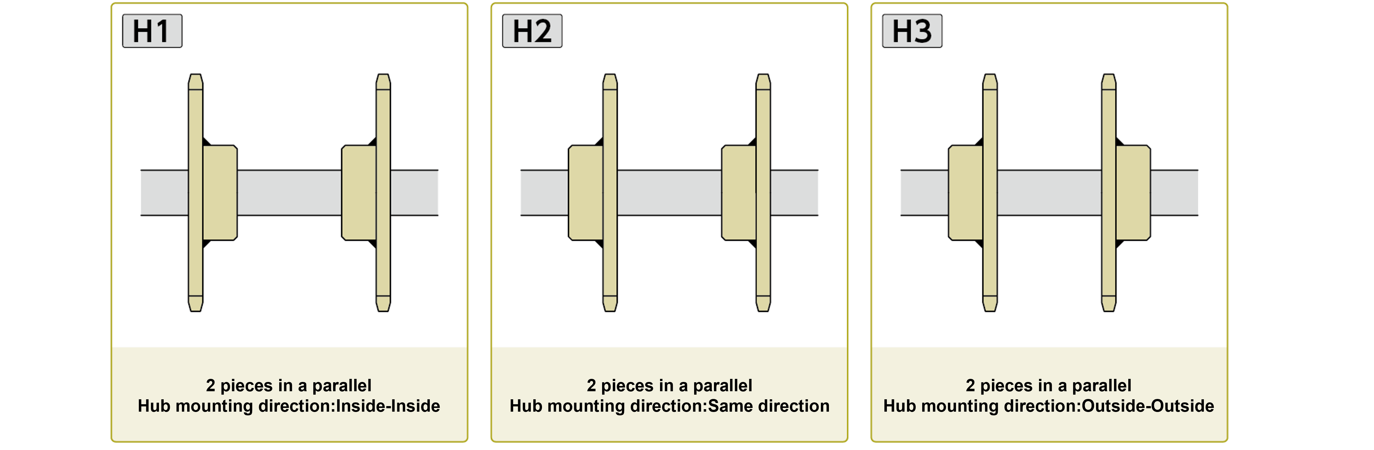
*For H1 and H3, the tap placement will be mirror Image. mirror Image For general sprockets used in parallel, the tap arrangement is machined symmetrically. Example: For D2M16-H1 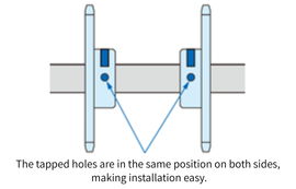
|
No note: None B: black oxide finish K: Electroless nickel-phosphorus plating C: Electrogalvanized (trivalent chromate treatment) |
Product List
Quick delivery models
This is an additional machining on pilot bore type stock items, so please check stock before ordering.
◎...Surface treatment required ○...Shaft hole processing required △...Shaft hole processing required (there are restrictions on processing)
Blue part is tooth tip hardening specification Light blue part is tooth tip non-hardening specification Colorless part is tooth tip non-hardening specification (tooth tip hardening treatment can be added)
Double Double pitch Sprocket
| Roller type Variety/tooth number |
steel | Stainless | |||||||||||||||||||
|---|---|---|---|---|---|---|---|---|---|---|---|---|---|---|---|---|---|---|---|---|---|
| S | R | S | R | ||||||||||||||||||
| RF2040S | RF2050S | RF2060S | RF2080S | RF2100S | RF2120S | RF2160S | RF2040R | RF2050R | RF2060R | RF2080R | RF2100R | RF2120R | RF2160R | RF2040S | RF2050S | RF2060S | RF2080S | RF2040R | RF2050R | RF2060R | |
| 912T | ◎ | ◎ | ◎ | ◎ | ◎ | ◎ | ◎ | ○ | ○ | ○ | ○ | ||||||||||
| 1000T | ◎ | ◎ | ◎ | ◎ | |||||||||||||||||
| 1012T | ◎ | ◎ | ◎ | ◎ | ○ | ○ | ○ | ○ | |||||||||||||
| 1100T | ◎ | ◎ | ◎ | ◎ | ◎ | ○ | ○ | ○ | ○ | ○ | |||||||||||
| 1112T | ◎ | ◎ | ◎ | ◎ | ○ | ○ | ○ | ○ | |||||||||||||
| 1200T | ◎ | ◎ | ◎ | ◎ | ◎ | ◎ | ◎ | ◎ | ○ | ○ | ○ | ○ | ○ | ○ | ○ | ||||||
| 1212T | ◎ | ◎ | ◎ | ◎ | ○ | ○ | ○ | ○ | |||||||||||||
| 1300T | ◎ | ◎ | ◎ | ◎ | ○ | ○ | ○ | ||||||||||||||
| 1400T | ◎ | ◎ | ◎ | ◎ | |||||||||||||||||
| 1500T | ◎ | ◎ | ◎ | ◎ | |||||||||||||||||
| 1600T | ◎ | ◎ | ◎ | ◎ | |||||||||||||||||
Double Plus Free Flow Chains sprocket
| Variety/tooth number | steel | ||||
|---|---|---|---|---|---|
| RF2030VRP | RF2040VRP | RF2050VRP | RF2060VRP | RF2080VRP | |
| 10T | ○ | ○ | ○ | ○ | △ |
Top chain sprocket
| Number of teeth | steel | Stainless | ||||||
|---|---|---|---|---|---|---|---|---|
| TT | TTP | TTU | TTUP | TPF | TPUSR | TPUN | TPUSR | |
| 800T | ◎ | |||||||
| 1000T | ◎ | ◎ | ||||||
| 1012T | ◎ | ◎ | ◎ | ◎ | ◎ | |||
| 1013T | ||||||||
| 1100T | ◎ | |||||||
| 1112T | ◎ | ◎ | ◎ | ◎ | ◎ | |||
| 1200T | ◎ | ◎ | ||||||
| 1212T | ◎ | ◎ | ◎ | ◎ | ◎ | |||
| 1300T | ◎ | |||||||
| 1500T | ◎ | ○ | ||||||
Machining contents
*Click to display detailed information.
| Shaft hole processing (L) | Keyway processing (K) | Tap hole processing (D) |
|---|---|---|
 |
 |
 |
|
・Processing dimensions are integers in 1mm increments only ・Processing tolerance...selectable |
・Parallel keyway only ・Processing tolerance...selectable |
・Processing size can be selected ・You can select up to two processing locations - Comes with a set screw |
B=A/2 |

If the tapped hole is long, |
|
・Hexagonal socket, - Plated or stainless steel body 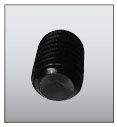
|
 Shaft hole machining dimensions list
In the case of JS9/P9 (new JIS)
| Applicable shaft hole diameter (mm) |
Keyway width (mm) |
Tsubaki Standard size |
Selected size |
|---|---|---|---|
| 10~12 | 4 | M4 | --- |
| 12~17 | 5 | M5 | M4 |
| 17~22 | 6 | M6 | M5 |
| 22~30 | 8 | M6 | M5, M8 |
| 30~38 | 10 | M8 | M6, M10 |
| 38~44 | 12 | M8 | M6, M10 |
| 44~50 | 14 | M8 | M6, M10 |
| 50~58 | 16 | M10 | M8, M12 |
| 58~65 | 18 | M10 | M8, M12 |
| 65~75 | 20 | M12 | M10, M16 |
| 75~85 | 22 | M12 | M10, M16 |
| 85~95 | 25 | M16 | M12, M20 |
| 95~110 | 28 | M16 | M12, M20 |
| 110~130 | 32 | M20 | M16 |
| 130~150 | 36 | M20 | M16 |
| 150~170 | 40 | M20 | M16 |
| 170~(200) | 45 | M24 | M20 |
If there is no keyway, the bore chamfer dimensions will be half of those in the table below.
In the case of F7 and E9 (old JIS)
| Applicable shaft hole diameter (mm) |
Keyway width (mm) |
Tsubaki Standard size |
Selected size |
|---|---|---|---|
| 10~13 | 4 | M4 | --- |
| 14~20 | 5 | M5 | M4 |
| 21~30 | 7 | M6 | M5 |
| 31~40 | 10 | M8 | M6, M10 |
| 41~50 | 12 | M8 | M6, M10 |
| 51~60 | 15 | M8 | M6, M10 |
| 61~70 | 18 | M10 | M8, M12 |
| 71~80 | 20 | M12 | M10, M16 |
| 81~95 | 24 | M12 | M10, M16 |
| 96~110 | 28 | M16 | M12, M20 |
| 111~125 | 32 | M20 | M16 |
| 126~140 | 35 | M20 | M16 |
| 141~160 | 38 | M20 | M16 |
| 161~170 | 42 | M20 | M16 |
Tsubaki standard shaft hole chamfer
| Shaft Hole Diameter | Shaft hole chamfer |
|---|---|
| 10~20 | 1 |
| 21~32 | 1.2 |
| 33~50 | 1.6 |
| 51~80 | 2.5 |
| 81~170 | 3 |
| Shaft Hole Diameter | Selectable chamfer amount | |||
|---|---|---|---|---|
| 10~17 | N | A | - | - |
| 18~44 | N | A | B | - |
| 45~170 | N | A | B | C |
*Some chamfer amounts cannot be selected depending on the size and hub type. Please check Drawing Library for details.
| Processing category | Double pitch | TT | For Double Plus Free Flow Chains | |||
|---|---|---|---|---|---|---|
| Shaft hole | key | Tap | ||||
| I | --- | 0 |  |
 |
 |
|
| II | 0 |  |
 |
 |
||
| III | 1 |  |
 |
 |
||
| 2 |  |
 |
 |
|||
| 3 |  |
 |
 |
|||
| 4 |  |
 |
 |
|||
| 5 |  |
 |
 |
|||
| IV | --- | 1 |  |
 |
 |
|
| 2 |  |
 |
 |
|||
| 3 |  |
 |
 |
|||
| 4 |  |
 |
 |
|||
| 5 |  |
 |
 |
|||
| H0 | None |
| H1 | Hub installation direction: Inner-inner |
| H2 | Hub installation direction: Same direction |
| H3 | Hub mounting direction: Outer-outer |
- - For parallel use, when two sprockets are used on the same axis, the keyway position is aligned in the specified installation direction.
- - Please select the hub mounting direction from the three patterns shown in the diagram below.
Hub installation direction image
| Ordering code | Specification |
|---|---|
| B | black oxide finish |
| K | Electroless nickel-phosphorus plating |
| C | Electrogalvanized (trivalent chromate treatment) |
others
| Limitations | Please contact us for inspection report and material certificate. (If submission is required, it will be treated as a general special form.) |
|---|
