Torque Limiter

- The most versatile friction type overload protective device
- - Can be attached to the shaft and power can be transmitted using roller chains, belts, or gears.
- - It will slip if an overload is applied and will automatically return to normal when the overload is removed.
- - Setting the slip torque is easy; just tighten the adjustment nut or adjustment bolt.
- -A wide range of sizes are available, allowing for a wide range of torque settings.
- -We also have a selection of sprockets and coupling types.
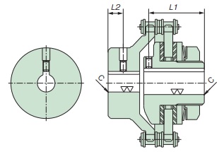
Structure

During normal operation, the center member is sandwiched between friction plates and pressurized by a disc spring, and rotation is transmitted by frictional force below the set torque.
When overloaded, if the torque exceeds the set value, the center member will slip between the friction plates. If the overload is released, it will Auto reset.
*The diagram above shows the structure of TL200 to TL350. For TL500 to TL700 and TL10 to TL20, the slip torque is set by tightening the adjustment bolt. Please refer to Instruction Manuals for details.
Specifications (standard model)
| Set torque range N・m | Backlash | Reset method |
|---|---|---|
| 1.0~9310 | None (only when driving in one direction) | Automatic |
(Note) Backlash will occur if the rotation direction is reversed.
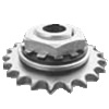
Torque Limiter with sprocket
>> Click here for sprockets with machined shaft holes
>> For set screws, chamfering and finishing click here

Torque Limiter Coupling
>> For set screws, chamfering and finishing click here
Specifications (standard model)
・Set screw position and size
| Torque Limiter | Torque Limiter side | Torque Limiter (coupling type) | |||
|---|---|---|---|---|---|
| Set screw | Set screw position (L1) | Set screw | Set screw position (L2) | ||
| TL200 | TL200-C | - | - | M 5× 5 | 8 |
| TL250 | TL250-C | M 5× 8 | 44 | M 5× 5 | 12 |
| TL350 | TL350-C | M 6×12 | 56 | M 6× 6 | 18 |
| TL500 | TL500-C | M 8×20 | 69 | M 8× 8 | 20 |
| TL700 | TL700-C | M10×20 | 90 | M10×10 | 33 |
| TL10 | TL10-C | M 8× 8 | 10 | M 8× 8 | 15 |
| TL14 | TL14-C | M10×10 | 12 | M10×10 | 20 |
| TL20 | TL20-C | M14×14 | 15 | M14×14 | 35 |
・Chamfering and finishing
| Shaft Hole Diameter | Chamfer dimensions |
|---|---|
| Φ25 or less | C0.5 |
| Φ50 or less | C1 |
| Φ125 or less | C1.5 |
| When the diameter exceeds Φ125 | C2 |
Catalogs and Instruction Manuals
Model number display
*Single unit type
| TL250 | - | 2 | - | B6.5 | - | TH20JD1 |
| | Size |
| Number of disc springs 1:1 2: 2 1L: Weak spring |
| Bush length (None without bush) |
| Shaft hole symbol |
|||
*With sprocket
| TL250 | - | 2 | - | 04022 | - | TH20JD1 | - | N49 |
| | Size |
| Number of disc springs |
| Sprocket model number |
| Shaft hole symbol |
| Torque setting value N・m |
||||
*Coupling type
| TL250 | - | 2 | C | - | TH18JD1 | X | CH30JD1 | - | N49 |
| | Size |
| | | |
| Coupling type |
| Torque Limiter side Shaft hole symbol |
| Coupling side Shaft hole symbol |
| Torque setting value N・m |
||||
| | Number of disc springs |
|||||||||
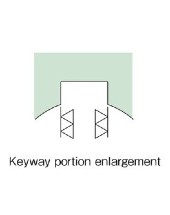
| Shaft hole diameter tolerance | Shaft Hole Diameter | Keyway tolerance | Set screw position | |
|---|---|---|---|---|
| T | H | 18 | J | D1 |
| C | H | 30 | J | D1 |
| T:トルクリミター側 C:カップリング側 | F:F7 G:G7 H:H7 J:JS7 P:P7 M:M7 N:N7 K:K7 R:R7 |
Shaft hole diameter is in 1mm increments |
J: New JIS Js9 (standard) P: New JIS P9 F: Old JIS F7 E: Old JIS E9 |
 [Click to enlarge] |
Note) The position of the set screw on Torque Limiter side is the position seen from the adjustment nut side, and the position of the set screw on the coupling side is the position seen from the hub end face.
■ Tsubaki model No. navigation
Product model number list
*Click on the model number to display detailed information.
| Set torque range N・m |
Single unit | Coupling Type | ||
|---|---|---|---|---|
| Shaft hole diameter range mm |
Model number | Coupling side Shaft hole diameter range mm |
Model number | |
| 1.0~2.0 | 9~14 | TL200-1L | 10~31 | TL200-1LC |
| 2.9~9.8 | TL200-1 | TL200-1C | ||
| 6.9~20 | TL200-2 | TL200-2C | ||
| 2.9~6.9 | 12~22 | TL250-1L | 15~38 | TL250-1LC |
| 6.9~27 | TL250-1 | TL250-1C | ||
| 14~54 | TL250-2 | TL250-2C | ||
| 9.8~20 | 18~25 | TL350-1L | 15~45 | TL350-1LC |
| 20~74 | TL350-1 | TL350-1C | ||
| 34~149 | TL350-2 | TL350-2C | ||
| 20~49 | 22~42 | TL500-1L | 20~65 | TL500-1LC |
| 47~210 | TL500-1 | TL500-1C | ||
| 88~420 | TL500-2 | TL500-2C | ||
| 49~118 | 32~64 | TL700-1L | 25~90 | TL700-1LC |
| 116~569 | TL700-1 | TL700-1C | ||
| 223~1080 | TL700-2 | TL700-2C | ||
| 392~1270 | 32~72 | TL10-16 | 35~95 | TL10-16C |
| 588~1860 | TL10-24 | TL10-24C | ||
| 882~2660 | 42~100 | TL14-10 | 40~118 | TL14-10C |
| 1960~3920 | TL14-15 | TL14-15C | ||
| 2450~4900 | 52~130 | TL20-6 | 45~150 | TL20-6C |
| 4610~9310 | TL20-12 | TL20-12C | ||
Selection
When using Torque Limiter in personnel transport equipment or lifting equipment, take measures on the equipment side to prevent accidents involving personnel or falls.
1. Based on the strength of the machine, load, and other conditions, determine the torque that should not be applied above this level and use this as the slip torque of Torque Limiter.
If this torque is unclear, calculate it from the rated output of the prime mover and the rotational speed of the shaft on which Torque Limiter is attached, and use 1.5 to 2 times that as the slip torque of Torque Limiter
please.
2. When determining the size of Torque Limiter, make sure that the slip torque falls within the range of Torque Limiter 's rated torque.
3. Check the dimension table to make sure that the maximum shaft hole diameter of Torque Limiter you have decided on is larger than the mounting shaft diameter.
If the mounting shaft diameter is large, use Torque Limiter that is one size larger.
4. Determine the appropriate length of bushing (see product model number page) based on the thickness of the center member to be clamped into Torque Limiter.
Refer to the bushing length listed in the dimension table and select the longest bushing possible, either one or a combination of multiple bushings, that does not exceed the thickness of the center member.
Selection and manufacturing of center members/detection of their movements
For details on selecting and manufacturing a sprocket or other part to be clamped in Torque Limiter as a center member, and on overload detection methods using a center member, please see here.
>> About the production and selection of center members and overload detection
When using Torque Limiter
・When purchasing Torque Limiter with a pilot bore, you will need to process the boss's shaft hole and keyway, manufacture the center member, and set the torque before attaching it to the shaft.
- As the friction coefficient decreases, the slip torque also decreases, so make sure that moisture, oil, etc. do not adhere to the friction plate.
If excessive retightening is performed as a countermeasure, the load on the friction plate via the disc spring will increase, and there is a possibility that the friction plate may crack.
- If the rotation speed is too high, the friction plate may become hot when it slips, causing the surface of the friction plate to carbonize and resulting in a decrease in strength, so do not use it at speeds above the maximum rotation speed.
・When used at extremely low speeds of 5 r/min or less, slip torque may decrease. Please consult us separately if you intend to use at extremely low speeds.

