Shock Guard TGM Series
- Sealed type with excellent environmental resistance
- - The structure is designed to prevent dust, oil, water, etc. from entering and oil from leaking.
- - The variation in adjacent trip torque is within ±5%.
- - The cam follower and pocket are engaged, so there is no phase misalignment between the drive side and the driven side.
- - When Shock Guard trips, the LS detection plate slides axially, activating the limit switch.
- -Long life, able to withstand over 100,000 trips.
- -Sprocket and coupling types are also available.
Minimum number of teeth on usable sprockets
・TGM series
| Model number | Minimum number of sprocket teeth | |||||||||||||||||
|---|---|---|---|---|---|---|---|---|---|---|---|---|---|---|---|---|---|---|
| RS25 | RS35 | RS40 | RS50 | RS60 | RS80 | RS100 | RS120 | |||||||||||
| TGM3 | ※30 | 22 | 17 | 15 | ||||||||||||||
| TGM6 | ※30 | 22 | 17 | 15 | ||||||||||||||
| TGM20 | ※34 | 24 | 19 | 16 | 14 | |||||||||||||
| TGM60 | ※32 | 26 | 21 | 18 | 15 | |||||||||||||
| TGM200 | ※37 | 30 | 26 | 20 | 17 | |||||||||||||
| TGM400 | ※41 | 35 | ※27 | 24 | 20 | |||||||||||||
| TGM800 | ※41 | 35 | ※27 | 24 | 20 | |||||||||||||
*The mark does not indicate the standard number of teeth.
(Note) Insert the joint link from the outside of the sprocket.
Note: The transmission capacity of the sprocket is not taken into consideration.
Video content
Structure
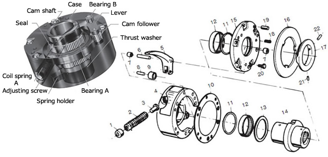
(1) Adjusting screw (2) Coil spring A (3) Spring seat (4) Case (5) Lever (6) Fulcrum pin (7) Bearing B (8) Roller pin
(9) Cam follower (10) Packing (11) Seal (12) Bearing A (13) Thrust washer (14) Cam shaft (15) Cover
(16) LS detection plate (17) Cam operating plate (18) Coil spring B (19) Spring pin (20) Hexagon bolt (21) Hexagon socket set screw
(22) Hexagon socket set screw
Operating principle
Please watch the animation to see the operating principle of the TGM series.
During normal operation (engaged)
Torque is transmitted through two-point contact between the cam follower and pocket.
The cam follower pocket is pressurized by a rectangular spring that presses firmly from the radial direction.
I am.
This means there is no backlash and it provides overload protection with highly accurate trip torque.
The return is Auto reset, so the cam follower returns to its original position in the pocket when operation resumes.
Since it is a two-point contact, there is no deviation from the original phase.
When overloaded (tripped)
When an overload occurs, the cam follower lifts out of its pocket and begins to roll on the outer surface of the camshaft.
As there are no sliding parts, the idling friction torque is small and it has excellent durability.
Furthermore, the structure is simple and the engagement is at one point, so high trip torque accuracy is not compromised.
Movement during overload (trip)
When Shock Guard trips due to an overload, the LS detection plate slides axially.
Limit switches can be activated to cut off power or sound an alarm.
The LS detection plate slides three times for one trip.
*Please refer to Instruction Manuals for information on overload detection using limit switches.
Specifications (standard model)
| Set torque range N・m | Repeated operating torque accuracy | Backlash | Reset method |
|---|---|---|---|
| 0.6~1060 | ±5% | None | Automatic |
Catalogs and Instruction Manuals
Model number display
*Single unit type
| TGM | 60 | - | TH30JDY | - | WS | - | N25 |
| | Series |
| Size |
| Shaft hole symbol |
| | | |
| Torque setting value N・m |
|||
| Spring specifications SS: Reinforced spring WS: Weak spring None: Standard spring |
|||||||
*Coupling type
| TGM | 60 | C | - | TH20JDY | X | CH30ED2 | - | WS | - | N98 |
| | Series |
| Size |
| | | |
| Shock Guard side Shaft hole symbol |
| Coupling side Shaft hole symbol |
| Spring specifications |
| Torque setting value N・m |
||||
| Coupling type |
||||||||||
| Shaft hole diameter tolerance | Shaft Hole Diameter | Keyway tolerance | Set screw position | ||
|---|---|---|---|---|---|
| T | H | 20 | J | DY | |
 |
|||||
| C | H | 30 | E | D2 | |
| T:ショックガード側 C:カップリング側 | F:F7 G:G7 H:H7 J:JS7 P:P7 M:M7 N:N7 K:K7 R:R7 |
Shaft hole diameter is in 1mm increments |
J: New JIS Js9 (standard) P: New JIS P9 F: Old JIS F7 E: Old JIS E9 |
 [Click to enlarge] |
|
Note) The position of the setscrew on Shock Guard side is the position seen from the adjustment nut side, and the position of the setscrew on the coupling side is the position seen from the hub end face.
■ Tsubaki model No. navigation
Product model number list
*Click on the model number to display detailed information.
| Set torque range N・m |
Single unit | Coupling Type | ||
|---|---|---|---|---|
| Shaft hole diameter range mm |
Model number | Coupling side Shaft hole diameter range mm |
Model number | |
| 0.6~1.5 | 10~14 | TGM3-T□□□□-WS | 14~30 | TGM3C-T□□□□XC□□□□-WS |
| 1.5~3.7 | TGM3-T□□□□ | TGM3C-T□□□□XC□□□□ | ||
| 2.5~6.4 | 10~14 | TGM6-T□□□□ | 14~30 | TGM6C-T□□□□XC□□□□ |
| 6.0~12 | TGM6-T□□□□-SS | TGM6C-T□□□□XC□□□□-SS | ||
| 3.7~12 | 14~20 | TGM20-T□□□□-WS | 14~32 | TGM20C-T□□□□XC□□□□-WS |
| 6.4~20 | TGM20-T□□□□ | TGM20C-T□□□□XC□□□□ | ||
| 7.3~23 | TGM20-T□□□□-SS | TGM20C-T□□□□XC□□□□-SS | ||
| 7.6~26 | 20~30 | TGM60-T□□□□-WS | 14~42 | TGM60C-T□□□□XC□□□□-WS |
| 20~69 | TGM60-T□□□□ | TGM60C-T□□□□XC□□□□ | ||
| 44~105 | TGM60-T□□□□-SS | TGM60C-T□□□□XC□□□□-SS | ||
| 30~98 | 28~50 | TGM200-T□□□□-WS | 20~55 | TGM200C-T□□□□XC□□□□-WS |
| 68~225 | TGM200-T□□□□ | TGM200C-T□□□□XC□□□□ | ||
| 101~289 | TGM200-T□□□□-SS | TGM200C-T□□□□XC□□□□-SS | ||
| 118~235 | 38~60 | TGM400-T□□□□-WS | 30~75 | TGM400C-T□□□□XC□□□□-WS |
| 225~451 | TGM400-T□□□□ | TGM400C-T□□□□XC□□□□ | ||
| 451~902 | 38~60 | TGM800-T□□□□ | 30~75 | TGM800C-T□□□□XC□□□□ |
| 532~1060 | TGM800-T□□□□-SS | TGM800C-T□□□□XC□□□□-SS | ||
Sizing
We will select Shock Guard that best suits your usage conditions from the entire Tsubaki Shock Guard series.
Please click on the "sizing" tab at the top of this page.
Back to top of this page
