Shock Guard TGH Series
- This type can be attached to a high-speed rotating shaft such as a direct motor connection, and is also compatible with high torque.
- - Repeated operating torque accuracy is within ±5%.
- In addition to the basic type, we also stock coupling and pulley types.
- - This function does not Auto reset, so after tripping due to overload, the rotation of the drive side is not transmitted to the driven side.
- -You can choose between one-position return (returning in only one position) or random return.
- One-position return: Returns to the original position in just one place. Suitable for phase alignment.
- Random return: You can return to multiple locations.
Structure
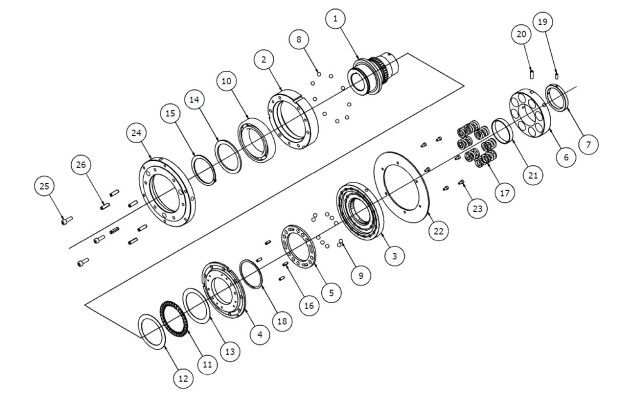
| (1) | Hub | (2) | Drive plate | (3) | Slide plate | (4) | Intermediate plate | (5) | Backup ring |
| (6) | Torque adjustment nut | (7) | lock collar | (8) | Drive ball (steel ball A) | (9) | steel ball B | (10) | ball bearings |
| (11) | Thrust bearing | (12) | Thrust washer | (13) | Support Ring A | (14) | Snap ring A | (15a,b) | Spring pin A |
| (16a,b) | Spring pin C | (17) | Coil spring | (18) | Coil spring (inner) | (19) | - | (20) | Hexagon socket set screw |
| (21) | Hexagon socket set screw | (22) | Torque Adjustment Spacer | (23) | adapter | (24) | Spring pin B | (25) | Hexagon socket head bolt |
| (26) | Spring washer | (27a,b) | Shim ring | (28) | Detection plate | (29) | Hexagon socket head bolt | (30a,b) | Tapered roller bearing |
| (31) | Pressure plate | (32) | Socket head cap screws | (33) | Spring washer | (34) | Bearing cover | (35) | Hex socket countersunk bolts |
| (36) | Spring holder | (37) | Hexagon bolt | (38) | Flat washer | (39) | Key plate | (40) | Hexagon socket head bolt |
| (41) | Hexagon socket set screw | (42a,b) | Grease nipple |
Operating principle
Normal (engaged)
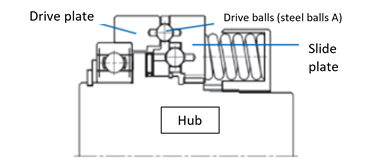
In the TGH series, several drive balls (steel balls A) are sandwiched between a drive plate and a slide plate, and power is transmitted while being pressurized by a spring.
Power enters through the hub, is transmitted to the slide plate which meshes with the involute spline, and is then transmitted to the drive plate via the drive balls (steel balls A).
The driven pulley and coupling are fixed to the adapter attached to the drive plate with spring pins and bolts.
When overloaded (tripped)
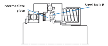
When an overload occurs, the drive balls (steel balls A) push the slide plate toward the spring, and while rotating, they jump out of each pocket on the drive plate, cutting off power.
After this, if the drive ball (steel ball A) continues to spin freely, it will enter a deep pocket in the slide plate, and steel ball B on the intermediate plate will support the spring load applied to the slide plate.
As a result, the drive ball (steel ball A) remains stuck in a deep pocket in the slide plate, and even if it continues to spin freely, it does not transmit power to the drive plate and continues to spin freely.
Specifications (standard model)
| Series | Set torque range N・m | Repeated operating torque accuracy | Reset method |
|---|---|---|---|
| Basic Type | 32~5050 | ±5% | manual |
| Coupling (NER) type | 32~5050 | ||
| Coupling (AFT) type | 32~5050 | ||
| Pulley Type | 32~2460 |
■Basic type: Customers can install gears and sprockets directly.
■Coupling (NER) type: This type combines NER couplings. It features high rigidity and no backlash.
■Coupling (AFT) Type: This type combines ATRAFLEX couplings. Its features include excellent vibration damping and shock absorption, easy installation, and compact design.
■ Pulley type: A type that combines pulleys.
Catalogs and Instruction Manuals
Model number display
*Basic type
| TGH | 75 | - | M | B | S | - | T | H | 70 | P | D2 | - | N1000 |
| | Series |
| size 28 40 50 75 100 |
| Spring Type L: Weak spring M: Medium spring H: Strong spring U: Super strong spring |
| | | | | | | | |
| | | | |
| Shock Guard side T |
| Shaft hole diameter tolerance F: F7 G: G7 H:H7 J:JS7 P: P7 |
| Shaft Hole Diameter (mm) |
| | | | |
| Set screw position D2 |
| Torque setting value (N・m) |
|||
| How to return No symbol: Random return S: One position return |
Keyway Tolerance J: New JIS Js9 P: New JIS P9 F: Old JIS F7 E: Old JIS E9 |
||||||||||||
| type B: Basic type |
|||||||||||||
*Coupling type
| TGH | 50 | - | L | CN | S | - | T | H | 30 | J | D2 | X | C | H | 60 | J | D3 | - | N200 |
| | Series |
| size 28 40 50 75 100 |
| Spring Type L: Weak spring M: Medium spring H: Strong spring U: Super strong spring |
| | | | | | | | |
| | | | | | | | | | |
| | | | | | | | |
| Shaft hole diameter tolerance F: F7 G: G7 H:H7 J:JS7 P: P7 |
| Shaft Hole Diameter (mm) |
| | | | |
| Set screw position D2 |
| | | | | | | | |
| Shaft hole diameter tolerance F: F7 G: G7 H:H7 J:JS7 P: P7 |
| Shaft Hole Diameter (mm) |
| | | | |
| Set screw position D0 to D8 |
| Torque setting value (N・m) |
||||
| Keyway Tolerance J: New JIS Js9 P: New JIS P9 F: Old JIS F7 E: Old JIS E9 |
Keyway Tolerance J: New JIS Js9 P: New JIS P9 F: Old JIS F7 E: Old JIS E9 |
||||||||||||||||||
| type CN: Coupling (NER) type CA: Coupling (AFT) type |
Shock Guard side T |
Coupling side C |
|||||||||||||||||
| | How to return No symbol: Random return S: One position return |
|||||||||||||||||||
* Pulley type
| TGH | 50 | - | H | P | S | - | T | H | 100 | J | D0 | - | N1500 | -TK |
| | Series |
| size 28 40 50 75 |
| Spring Type L: Weak spring M: Medium spring H: Strong spring U: Super strong spring |
| | | | | | | | |
| | | | |
| Shock Guard side T |
| Shaft hole diameter tolerance F: F7 G: G7 H:H7 J:JS7 P: P7 |
| Shaft Hole Diameter (mm) |
| | | | |
| Set screw position D0 |
| Torque setting value (N・m) |
| special shape |
|||
| How to return No symbol: Random return S: One position return |
Keyway Tolerance J: New JIS Js9 P: New JIS P9 F: Old JIS F7 E: Old JIS E9 |
|||||||||||||
| type P: Pulley type |
||||||||||||||
Product model number list
*Click on the model number to display detailed information.
| Size | Spring Type | torque N・m |
Basic Type | Pulley Type | |||||
|---|---|---|---|---|---|---|---|---|---|
| Shaft hole diameter range mm |
Model | Shaft hole diameter range mm |
Model | ||||||
| Minimum | Maximum | Minimum | Maximum | Minimum | Maximum | ||||
| 28 | L | 32 | 80 | 12 | 28 | TGH28-LB | 12 | 36 (35) |
TGH28-LP |
| M | 64 | 160 | TGH28-MB | TGH28-MP | |||||
| H | 96 | 240 | TGH28-HB | TGH28-HP | |||||
| U | 128 | 320 | TGH28-UB | TGH28-UP | |||||
| 40 | L | 60 | 150 | 17 | 40 | TGH40-LB | 17 | 50 | TGH40-LP |
| M | 120 | 300 | TGH40-MB | TGH40-MP | |||||
| H | 180 | 450 | TGH40-HB | TGH40-HP | |||||
| U | 280 | 700 | TGH40-UB | TGH40-UP | |||||
| 50 | L | 80 | 200 | 20 | 50 | TGH50-LB | 20 | 58 (56) |
TGH50-LP |
| M | 160 | 400 | TGH50-MB | TGH50-MP | |||||
| H | 320 | 800 | TGH50-HB | TGH50-HP | |||||
| U | 480 | 1200 | TGH50-UB | TGH50-UP | |||||
| 75 | L | 246 | 615 | 50 | 75 (72) |
TGH75-LB | 50 | 80 (79) |
TGH75-LP |
| M | 492 | 1230 | TGH75-MB | TGH75-MP | |||||
| H | 738 | 1845 | TGH75-HB | TGH75-HP | |||||
| U | 984 | 2460 | TGH75-UB | TGH75-UP | |||||
| 100 | L | 400 | 1000 | 60 | 100 (95) |
TGH100-LB | - | ||
| M | 800 | 2000 | TGH100-MB | ||||||
| H | 1600 | 4000 | TGH100-HB | ||||||
| U | 2020 | 5050 | TGH100-UB | ||||||
| Size | Spring Type | torque N・m |
Coupling (NER) type | Coupling (AFT) type | |||||||||
|---|---|---|---|---|---|---|---|---|---|---|---|---|---|
| Shock Guard side Shaft hole diameter range mm |
Coupling side Shaft hole diameter range mm |
Model | Shock Guard side Shaft hole diameter range mm |
Coupling side Shaft hole diameter range mm |
Model | ||||||||
| Minimum | Maximum | Minimum | Maximum | Minimum | Maximum | Minimum | Maximum | Minimum | Maximum | ||||
| 28 | L | 32 | 80 | 12 | 28 | 25 | 65 (61) |
TGH28-LCN | 12 | 28 | 17 | 55 | TGH28-LCA |
| M | 64 | 160 | TGH28-MCN | TGH28-MCA | |||||||||
| H | 96 | 240 | TGH28-HCN | TGH28-HCA | |||||||||
| U | 128 | 320 | TGH28-UCN | TGH28-UCA | |||||||||
| 40 | L | 60 | 150 | 17 | 40 | 25 | 85 (80) |
TGH40-LCN | 17 | 40 | 22 | 60 | TGH40-LCA |
| M | 120 | 300 | TGH40-MCN | TGH40-MCA | |||||||||
| H | 180 | 450 | TGH40-HCN | TGH40-HCA | |||||||||
| U | 280 | 700 | TGH40-UCN | TGH40-UCA | |||||||||
| 50 | L | 80 | 200 | 20 | 50 | 50 | 90 (84) |
TGH50-LCN | 20 | 50 | 22 | 80 | TGH50-LCA |
| M | 160 | 400 | TGH50-MCN | TGH50-MCA | |||||||||
| H | 320 | 800 | TGH50-HCN | TGH50-HCA | |||||||||
| U | 480 | 1200 | TGH50-UCN | TGH50-UCA | |||||||||
| 75 | L | 246 | 615 | 50 | 75 (72) |
60 | 105 (99) |
TGH75-LCN | 50 | 75 (72) |
42 | 110 | TGH75-LCA |
| M | 492 | 1230 | TGH75-MCN | TGH75-MCA | |||||||||
| H | 738 | 1845 | TGH75-HCN | TGH75-HCA | |||||||||
| U | 984 | 2460 | TGH75-UCN | TGH75-UCA | |||||||||
| 100 | L | 400 | 1000 | 60 | 100 (95) |
80 | 125 (119) |
TGH100-LCN | 60 | 100 (95) |
42 | 140 | TGH100-LCA |
| M | 800 | 2000 | TGH100-MCN | TGH100-MCA | |||||||||
| H | 1600 | 4000 | TGH100-HCN | TGH100-HCA | |||||||||
| U | 2020 | 5050 | TGH100-UCN | TGH100-UCA | |||||||||
*The ( ) part indicates the maximum shaft hole diameter when processed according to the old JIS. The new JIS conforms to "JIS B 1301-1996", and the old JIS conforms to "JIS B 1301-1959".
Option
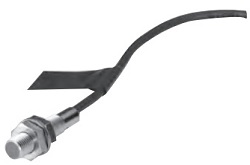
TG sensor
This is a proximity switch type overload detection sensor designed specifically for Shock Guard. It can detect an overload on Shock Guard (movement of the plate in the axial direction) and stop the motor or issue an alarm.
| AC type | DC type | ||
|---|---|---|---|
| Model number | TGS8 | TGS8DN | |
| power supply Voltage |
Rating | AC24~240V | - |
| Usable range | AC20~264V(50/60Hz) | DC10~30V | |
| Current consumption | 1.7mA or less (at AC200V) | 16mA or less | |
| Control output (switching capacity) | 5~100mA | Max 200mA | |
| indicator light | Operation display | ||
| Ambient temperature | -25 to +70°C (but do not freeze) | ||
| Ambient humidity | 35~95% RH | ||
| Output format | - | NPN | |
| Operation form | NC (センサプレートを検知していない時の出力開閉状態を表します) |
||
| Insulation resistance | 50MΩ or more (DC500V megger) between all live parts and case | ||
| mass | Approximately 45g (2m cord length) | Approximately 56g (2m cord length) | |
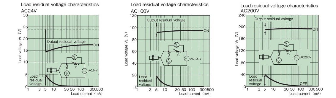
| Residual voltage | >> See characteristic data | 2.0V or less (load current 200mA, cord length 2m) | |
| Instruction Manuals | TG sensor TGS8 | TG sensor TGS8DN | |
Load residual voltage characteristics
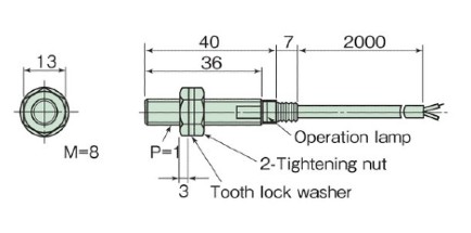
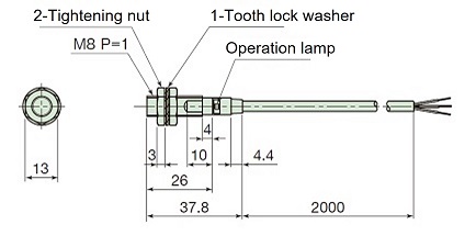
Dimensions
AC type TGS8
DC type TGS8DN
Sizing
We will select Shock Guard that best suits your usage conditions from the entire Tsubaki Shock Guard series.
Please click on the "sizing" tab at the top of this page.
Back to top of this page
