Shock Guard TGE Series
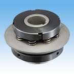
- A type that allows for a wide range of torque settings with the same size
- - Bearings are used and the center member is attached to the bearing, so runout is smaller than that of the TGB series.
- - You can choose between Type 1, which can be fitted with small diameter sprockets and wide pulleys, and Type 3, which can be fitted directly with A-type sprockets and pulleys.
- - After removing the cause of the overload, simply rotate the drive side and the gears will automatically re-engage.
- - The arrangement of the balls and pockets that serve as torque transmission elements is a unique combination that only meshes in one place.
Minimum number of teeth on usable sprockets
・TGE series
Type 1
| Model number | Minimum number of sprocket teeth | |||||||||||
|---|---|---|---|---|---|---|---|---|---|---|---|---|
| RS35 | RS40 | RS50 | RS60 | RS80 | ||||||||
| TGE17-1 | 18 | 14 | 12 | - | - | |||||||
| TGE25-1 | 25 | 20 | 17 | 15 | 12 | |||||||
| TGE35-1 | 32 | 25 | 20 | 18 | 14 | |||||||
| TGE50-1 | - | 31 | 26 | 22 | 17 | |||||||
This is the minimum number of teeth when the boss part of the special B-type sprocket is attached to the connection adapter.
Type 3
| Model number | Minimum number of sprocket teeth | |||||||||||
|---|---|---|---|---|---|---|---|---|---|---|---|---|
| RS35 | RS40 | RS50 | RS60 | RS80 | ||||||||
| TGE17-3 | 23 | 18 | 15 | - | - | |||||||
| TGE25-3 | 32 | 25 | 21 | 18 | 14 | |||||||
| TGE35-3 | 39 | 30 | 25 | 21 | 17 | |||||||
| TGE50-3 | - | 40 | 33 | 28 | 22 | |||||||
Note: The transmission capacity of the sprocket is not taken into consideration.
Structure
TGE17-1 to 50-1 (Type 1)
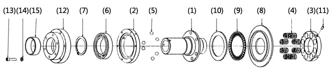
(1) Hub (2) Drive plate (3) Adjusting nut (4) Coil spring (5) Drive ball (6) Ball bearing
(7) Snap ring (8) Cover (9) Thrust bearing (10) Thrust race (11) Hexagon socket head bolt (12) Mounting adapter
(13) Hexagon socket head bolt (14) Spring washer (15) Dry bearing
TGE17-3 to 50-3 (Type 3)

(1) Hub (2) Drive plate (3) Adjusting nut (4) Coil spring (5) Drive ball (6) Ball bearing
(7) Snap ring (8) Cover (9) Thrust bearing (10) Thrust race (11) Hexagon socket set screw
(12) Hexagon socket set screw
Operating principle
Please watch the animation to see the operating principle of the TGE series.
During normal operation (engaged)
With the TGE series, power enters through the hub and is transmitted to the output drive plate via the drive balls (or vice versa).
Sprockets and Belt Sprockets are attached directly to this drive plate with bolts.
There are holes in the flange of the hub that fit several drive balls, and the drive balls are arranged in these holes.
The drive plate on the output side has pockets for the drive balls, which are compressed by a coil spring through a thrust race to transmit power.

When overloaded (tripped)
When an overload occurs, the drive ball pushes the thrust race up towards the coil spring, and the drive
It pops out of the pocket in the plate and cuts off power.
At this time, the cover moves toward the coil spring, and by detecting this movement with a TG sensor, etc.,
After an overload occurs, the drive source can be automatically stopped easily.
Reset method
After an overload, if you restart it, it will automatically return to its original position within one rotation.
The TGE series will continuously reset if rotation continues after operation, so after an overload occurs, detect the overload with a TG sensor or similar device and immediately stop the drive source.
Specifications (standard model)
| Set torque range N・m | Repeated operating torque accuracy | Backlash | Reset method |
|---|---|---|---|
| 1.0~700 | ±5% | Small | Automatic |
■ Type 1: Small diameter sprockets and wide pulleys can be installed
■ Type 3: A general-purpose type that can be directly mounted to A-type sprockets and pulleys
Catalogs and Instruction Manuals
Model number display
*Single unit type
| TGE | 50 | - | M | 3 | - | TH40JD2 | - | N245 |
| | Series |
| Size |
| | | | |
| type 1: Type 1 3: Type 3 |
| Shaft hole symbol |
| Torque setting value N・m |
|||
| Spring strength L: Weak spring M: Medium spring H: Strong spring |
||||||||
| Shaft hole diameter tolerance | Shaft Hole Diameter | Keyway tolerance | Set screw position | |
|---|---|---|---|---|
| T | H | 40 | J | D2 |
| T:ショックガード側 | F:F7 G:G7 H:H7 |
Shaft hole diameter is in 1mm increments |
J: New JIS Js9 (standard) P: New JIS P9 F: Old JIS F7 |
 [Click to enlarge] |
■ Tsubaki model No. navigation
Product model number list
*Click on the model number to display detailed information.
| Set torque range N・m |
Type 1 | Type 3 | ||
|---|---|---|---|---|
| Shaft hole diameter range mm |
Model number | Shaft hole diameter range mm |
Model number | |
| 1.0~5.0 | 12~15 | TGE17-L1 | 12~17 | TGE17-L3 |
| 2.0~10 | TGE17-M1 | TGE17-M3 | ||
| 4.0~20 | TGE17-H1 | TGE17-H3 | ||
| 5.0~25 | 12~22 | TGE25-L1 | 12~25 | TGE25-L3 |
| 10~50 | TGE25-M1 | TGE25-M3 | ||
| 20~100 | TGE25-H1 | TGE25-H3 | ||
| 20~100 | 17~32 | TGE35-L1 | 17~35 | TGE35-L3 |
| 40~200 | TGE35-M1 | TGE35-M3 | ||
| 80~400 | TGE35-H1 | TGE35-H3 | ||
| 30~200 | 27~48 | TGE50-L1 | 27~50 | TGE50-L3 |
| 60~400 | TGE50-M1 | TGE50-M3 | ||
| 120~700 | TGE50-H1 | TGE50-H3 | ||
option
TG sensor
This is a proximity switch type overload detection sensor designed specifically for Shock Guard. It can detect an overload on Shock Guard (movement of the plate in the axial direction) and stop the motor or issue an alarm.
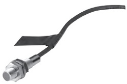
| AC type | DC type | ||
|---|---|---|---|
| Model number | TGS8 | TGS8DN | |
| power supply Voltage |
Rating | AC24~240V | - |
| Usable range | AC20~264V(50/60Hz) | DC10~30V | |
| Current consumption | 1.7mA or less (at AC200V) | 16mA or less | |
| Control output (switching capacity) | 5~100mA | Max 200mA | |
| indicator light | Operation display | ||
| Ambient temperature | -25 to +70°C (but do not freeze) | ||
| Ambient humidity | 35~95% RH | ||
| Output format | - | NPN | |
| Operation form | NC (センサプレートを検知していない時の出力開閉状態を表します) |
||
| Insulation resistance | 50MΩ or more (DC500V megger) between all live parts and case | ||
| mass | Approximately 45g (2m cord length) | Approximately 56g (2m cord length) | |
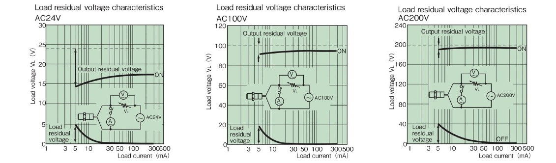
| Residual voltage | >> See characteristic data | 2.0V or less (load current 200mA, cord length 2m) | |
| Instruction Manuals | TG sensor TGS8 | TG sensor TGS8DN | |
Load residual voltage characteristics
Dimensions
AC type TGS8
DC type TGS8DN
Sizing
We will select Shock Guard that best suits your usage conditions from the entire Tsubaki Shock Guard series.
Please click on the "sizing" tab at the top of this page.
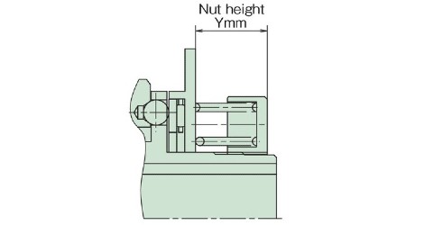
Back to top of this pageTorque adjustment
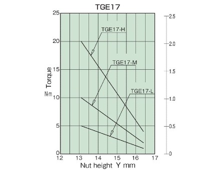
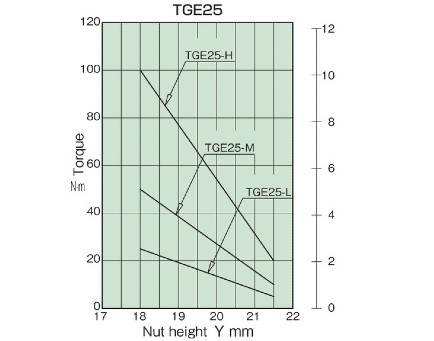
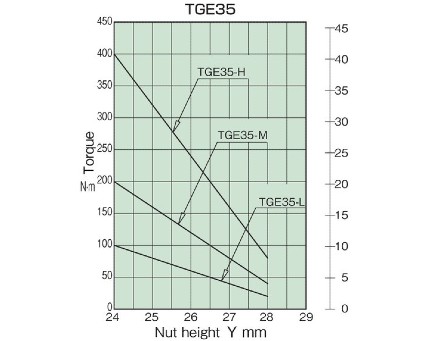
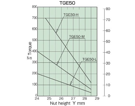
1. Read the nut height value corresponding to the required torque from the torque correlation diagram, and tighten the adjustment nut to this value (see diagram below).
To tighten the adjustment nut, loosen the set screws in two places, then place a hook wrench (see table below, sold separately) in the notch on the outside of the adjustment nut and turn it.
The torque of the product does not necessarily match the correlation diagram below, so please use it as a guide.
| Size | TGE25 | TGE35 | TGE50 |
|---|---|---|---|
| Spanner No. | FK-0070 | FK-0092 | FK-0105 |
2. Once the torque has been determined, you can add that value to the nameplate, so that even if you disassemble the product for maintenance, you can easily return to the previous set torque.
In addition, you can make the reproduction more accurate by stamping a match mark on the end face of the hub on the nut.
Torque correlation diagram