Torque Keeper

- Tsubaki's unique slipping clutch and brake
- - Fine chemicals are used for the friction plates, so you can expect a long life.
- - Torque fluctuation is minimal and slip torque is transmitted smoothly.
- - Stable torque transmission even with frequent repeated slippage.
- -Coupling types are also available.
Features
Stable slip torque
Torque fluctuation is minimal and slip torque is transmitted smoothly.
Torque Keeper

[Click to enlarge]
General brakes

Compared to our company: Same torque range
[Click to enlarge]
Accurate torque reproducibility
Even with high-frequency repeated slip torque,
Stable torque transmission is possible.
Intermittent slip

[Click to enlarge]
Long life
Special fine chemical fibers are used for the friction plates,
Longer life than other brake linings
You can look forward to it.
Applicable use
Accumulation
The stopper action allows Torque Keeper to slip stably, stopping the driven side in a fixed position.
Application Examples
Braking
・Intermittent slip
Torque Keeper repeatedly slips and engages, maintaining a stable torque on the driven side.
Application Examples
・Continuous slip
A brake for continuously driven mechanical devices.
Application Examples
dragging
The slip of Torque Keeper provides a stable load to the machine.
Application Examples
For transfer
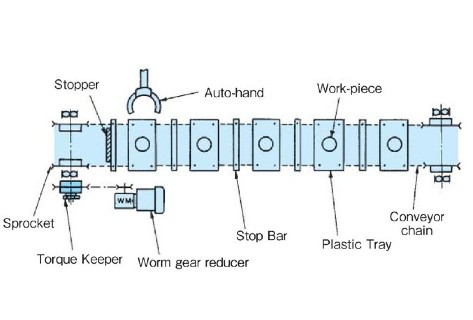
Chain conveyor
When the stop bar hits the stopper, Torque Keeper slips and the conveyor stops.
When the stopper is released, Torque Keeper is connected and the conveyor is driven.
For parking
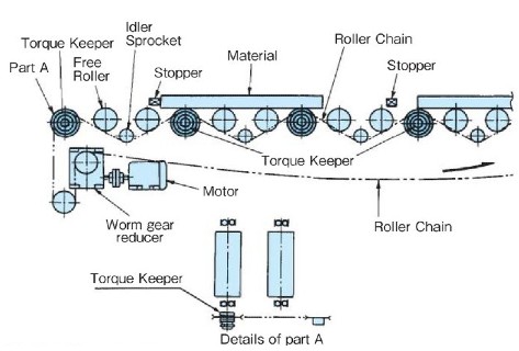
Roller Conveyor
The roller chain is driven continuously. When the material hits the stopper, Torque Keeper at that point slips and the material stops.
When the stopper is released, Torque Keeper is in a connected state and the material is driven again.
Intermittent slip
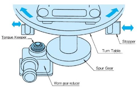
Multi-story parking lot turntable
Rotate the car leaving the parking lot toward the exit.
When the table reaches the correct position, it hits a stopper and stops.
At this time, Torque Keeper slips to protect the drive unit.
Continuous Slip
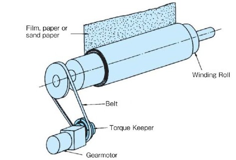
Winding of film, paper, sandpaper, etc.
Torque Keeper rotates at a low speed and slips while applying stable tension to film, paper, sandpaper, etc.
For load
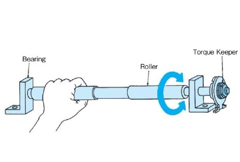
List Roller
Grip the roller and rotate it to strengthen your wrists.
Torque Keeper 's stable and smooth slip torque
Apply a load to the roller.
For tightening

tightening machine
Torque Keeper 's stable torque tightens bolts, nuts, valves, etc. at a constant torque.
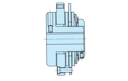
Structure
TFK20・TFK25・TFK35

[Click to enlarge]
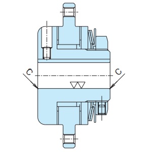
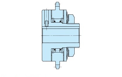
TFK50・TFK70

[Click to enlarge]
Specifications (standard model)
| Set torque range N・m | Backlash | Reset method |
|---|---|---|
| 0.6~650 | None (only when driving in one direction) | Automatic |
(Note) Backlash will occur if the rotation direction is reversed.
Catalogs and Instruction Manuals
Model number display
*Single unit type
| TFK35 | - | 1 | - | TH20JD1 | - | N25 |
| | Size |
| Number of disc springs 1:1 2: 2 1L: Weak spring |
| Shaft hole symbol |
| Torque setting value N・m |
|||
*Coupling type
| TFK25 | - | 1 | C | - | TH20JD1 | X | CH20JD5 | - | N16 |
| | Size |
| | | |
| Coupling type |
| Torque Keeper side Shaft hole symbol |
| Coupling side Shaft hole symbol |
| Torque setting value N・m |
||||
| | Number of disc springs |
|||||||||
| Shaft hole diameter tolerance | Shaft Hole Diameter | Keyway tolerance | Set screw position | |
|---|---|---|---|---|
| T | H | 20 | J | D1 |
| C | H | 20 | J | D5 |
| T:トルクキーパー側 C:カップリング側 | F:F7 G:G7 H:H7 J:JS7 P:P7 M:M7 N:N7 K:K7 R:R7 |
Shaft hole diameter is in 1mm increments |
J: New JIS Js9 (standard) P: New JIS P9 F: Old JIS F7 E: Old JIS E9 |
 [Click to enlarge] |
Note) The position of the set screw on Torque Keeper side is the position seen from the adjustment nut side, and the position of the set screw on the coupling side is the position seen from the hub end face.
■ Tsubaki model No. navigation
Product model number list
*Click on the model number to display detailed information.
| Set torque range N・m |
Single unit | Coupling Type | ||
|---|---|---|---|---|
| Shaft hole diameter range mm |
Model number | Coupling side Shaft hole diameter range mm |
Model number | |
| 0.6~1.1 | 9~14 | TFK20-1L | 10~26 | TFK20-1LC |
| 1.8~5.8 | TFK20-1 | TFK20-1C | ||
| 4.0~11 | TFK20-2 | TFK20-2C | ||
| 1.8~4.1 | 12~22 | TFK25-1L | 13~29 | TFK25-1LC |
| 4.0~16 | TFK25-1 | TFK25-1C | ||
| 7.9~32 | TFK25-2 | TFK25-2C | ||
| 5.9~11 | 19~25 | TFK35-1L | 15~35 | TFK35-1LC |
| 12~44 | TFK35-1 | TFK35-1C | ||
| 21~89 | TFK35-2 | TFK35-2C | ||
| 12~29 | 22~42 | TFK50-1L | 20~47 | TFK50-1LC |
| 29~125 | TFK50-1 | TFK50-1C | ||
| 53~252 | TFK50-2 | TFK50-2C | ||
| 30~70 | 32~64 | TFK70-1L | 21~63 | TFK70-1LC |
| 70~341 | TFK70-1 | TFK70-1C | ||
| 134~650 | TFK70-2 | TFK70-2C | ||
Selection
When using Torque Keeper in personnel transport or lifting equipment, please take measures on the equipment side to prevent accidents involving personnel or falls.
1. Determine the usage conditions in the table below according to the application above, and then determine the size from the TN curve diagram. >> Click here for the TN curve diagram
| Applicable use | Usage conditions | Determining size |
|---|---|---|
| Accumulation |
Determine the following items for each conveyor's Torque Keeper. 1. Slip torque 2. Slip rotation speed 3. Slip time (conveyor stop time) 4. Connection time (conveyor operation time) 5. Daily usage time |
The slip torque and slip rotation speed are If the slip time is longer than the connection time, or if the usage time exceeds 8 hours per day, |
| Braking |
Determine the following items for Torque Keeper of each machine device. 1. Brake torque 2. Rotation speed 3. Slip time (duration of braking) 4. Engagement time (time when the brake is not in operation) 5. Daily usage time However, in the case of continuous slip, steps 3 and 4 are not necessary. |
The brake torque and rotation speed are If the slip time is longer than the connection time, or if the usage time exceeds 8 hours per day, |
| dragging |
Determine the following items for Torque Keeper of each machine device. 1. Slip torque 2. Slip rotation speed 3. Slip time 4. Connection time 5. Daily usage time |
Slip torque and slip rotation speed If the slip time is longer than the connection time, or if the usage time exceeds 8 hours per day, |
 We recommend using it within 10 minutes.
2. Check that the shaft hole range of the determined Torque Keeper satisfies the shaft diameter to be installed.
3. Slip torque setting (Please refer to Instruction Manuals for details.)
Check whether the shaft hole range of the determined Torque Keeper satisfies the shaft diameter to be installed.
1. Please note that if water, oil, or other substances get into the friction surface, the torque will decrease and stable slip torque will not be obtained.
2. The TN curve applies to ambient temperatures up to 40°C. If this range is exceeded, please contact us.
3. If the slip torque for the shaft diameter you are using is smaller than the set torque range of Torque Keeper, please contact us.
4. Backlash will occur if the direction of rotation is reversed. This product cannot be used in devices where backlash is unacceptable.
Drive member manufacturing/chamfering, finishing, set screws
Manufacturing of drive members
For recommended machining dimensions for drive members such as sprockets, please refer to the product model number page.
When installing a sprocket as a drive member, refer to the table below for the minimum number of teeth on the sprocket.
| Model number | Sprocket used | ||||||
|---|---|---|---|---|---|---|---|
| RS35 | RS40 | RS50 | RS60 | RS80 | RS100 | RS120 | |
| TFK20 | 32 | 25 | |||||
| TFK25 | 35 | 28 | 23 | 20 | 16 | ||
| TFK35 | △33 (34) |
28 | 24 | 19 | 16 | 14 | |
| TFK50 | 45 | △37 (38) |
△31 (32) |
24 | 20 | 18 | |
| TFK70 | △47 (48) |
△39 (40) |
△31 (32) |
25 | 22 | ||
- Note 1) It is recommended that you use a roller chain that can be used Lube-free.
- Note 2) △ marks are not standard A-type sprockets. If using a standard stock sprocket, please use the number of teeth in parentheses.
Chamfering and finishing / Set screw position and size
Chamfering and finishing
| Shaft Hole Diameter | Chamfer dimensions |
|---|---|
| Φ25 or less | C0.5 |
| Φ50 or less | C1 |
| Φ125 or less | C1.5 |
| When the diameter exceeds Φ125 | C2 |
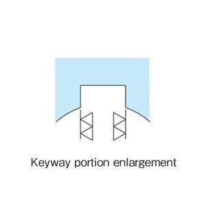
Shaft diameter and keyway specifications
- - The tolerance of the shaft hole diameter is H7.
- - The keyway is the new JIS (JIS B 1301-1996) "normal type."
- - Set screws are included when shipped.
Unit: mm
| Torque Keeper Model Number | Torque Keeper side |
Coupling side (Coupling type only) |
|||
|---|---|---|---|---|---|
| Set screw | Set screw position (L1) *Note 1 | Set screw | Set screw position (L2) *Note 2 | ||
| TFK20 | TFK20-C | M5 X 8 | 32 | M5 X 5 | 10.5 |
| TFK25 | TFK25-C | M5 X 8 | 42 | M6 X 8 | 10.5 |
| TFK35 | TFK35-C | M6 X 12 | 55 | M6 X 8 | 13.5 |
| TFK50 | TFK50-C | M8 X 20 | 69 | M8 X 12 | 20.5 |
| TFK70 | TFK70-C | M10 X 20 | 88 | M8 X 12 | 20.5 |
*Note 1) L1 is the distance from the end face of Torque Keeper body to the center of the set screw.
*Note 2) L2 is the distance from the end face of the coupling to the center of the set screw.
Special specification examples
Please contact us regarding special specifications.
Multi-plate Torque Keeper
| Model number | TFK35W-2 |
|---|---|
| Specification | Shaft diameter: Φ25 Torque setting range: 45 to 196 N・m {4.6 to 20 kgf・m} |
Cam clutch built-in Torque Keeper
| Model number | TFK35LD-1 |
|---|---|
| Specification | Maximum shaft hole diameter: Φ25 Torque setting range: 11 to 43 N・m {1.1 kgf・m to 4.4 kgf・m} |
| Main uses | After tightening bolts, nuts, valves, etc. to a certain torque, Mechanical devices that need to be loosened. |

