Q&A Top chain
We have posted frequently asked questions from customers in Q&A format. Please click on the question to proceed to the answer.
Words in Q&Aof
Top chain in general
Plastic top chain, Plastic block chain
Plastic modular chain

| Q1 | What are the classifications of Top chain? | |||||||||||||||||||||||||||||||||||||||||||||||||||||||||||||||||||||||||||||||||||||||||||||||||||||||||||||||||||||||||||||||||||||||||||||||||||||||||||||||||||||||||||||||||||||||||||||||||||||||||||||||||||||||||||||||||||||||||||||||||||||||||||||||||||||||||||||||||||||||||||||||||||||||||||||||||||||||||||||||||||||||||||||||||||||||||||||||||||||||||||||||||||||||||||||||||||||||||||||||||||||||||||||||||||||||||||||||||||||||||||||||||||||||||||||||||||||||||||||||||||||||||||||||||||||||||||||||||||||||||||||||||||||||||||||||||||||||||||||||||||||||||||||||||||||||||||||||||||||||||||||||||||||||||||||||||||||||||||||||||||||||||||||||||||||||||||||||||||||||||||||||||||||||||||||||||||||||||||||||||||||||||||||||||||||||||||||||||||
|---|---|---|---|---|---|---|---|---|---|---|---|---|---|---|---|---|---|---|---|---|---|---|---|---|---|---|---|---|---|---|---|---|---|---|---|---|---|---|---|---|---|---|---|---|---|---|---|---|---|---|---|---|---|---|---|---|---|---|---|---|---|---|---|---|---|---|---|---|---|---|---|---|---|---|---|---|---|---|---|---|---|---|---|---|---|---|---|---|---|---|---|---|---|---|---|---|---|---|---|---|---|---|---|---|---|---|---|---|---|---|---|---|---|---|---|---|---|---|---|---|---|---|---|---|---|---|---|---|---|---|---|---|---|---|---|---|---|---|---|---|---|---|---|---|---|---|---|---|---|---|---|---|---|---|---|---|---|---|---|---|---|---|---|---|---|---|---|---|---|---|---|---|---|---|---|---|---|---|---|---|---|---|---|---|---|---|---|---|---|---|---|---|---|---|---|---|---|---|---|---|---|---|---|---|---|---|---|---|---|---|---|---|---|---|---|---|---|---|---|---|---|---|---|---|---|---|---|---|---|---|---|---|---|---|---|---|---|---|---|---|---|---|---|---|---|---|---|---|---|---|---|---|---|---|---|---|---|---|---|---|---|---|---|---|---|---|---|---|---|---|---|---|---|---|---|---|---|---|---|---|---|---|---|---|---|---|---|---|---|---|---|---|---|---|---|---|---|---|---|---|---|---|---|---|---|---|---|---|---|---|---|---|---|---|---|---|---|---|---|---|---|---|---|---|---|---|---|---|---|---|---|---|---|---|---|---|---|---|---|---|---|---|---|---|---|---|---|---|---|---|---|---|---|---|---|---|---|---|---|---|---|---|---|---|---|---|---|---|---|---|---|---|---|---|---|---|---|---|---|---|---|---|---|---|---|---|---|---|---|---|---|---|---|---|---|---|---|---|---|---|---|---|---|---|---|---|---|---|---|---|---|---|---|---|---|---|---|---|---|---|---|---|---|---|---|---|---|---|---|---|---|---|---|---|---|---|---|---|---|---|---|---|---|---|---|---|---|---|---|---|---|---|---|---|---|---|---|---|---|---|---|---|---|---|---|---|---|---|---|---|---|---|---|---|---|---|---|---|---|---|---|---|---|---|---|---|---|---|---|---|---|---|---|---|---|---|---|---|---|---|---|---|---|---|---|---|---|---|---|---|---|---|---|---|---|---|---|---|---|---|---|---|---|---|---|---|---|---|---|---|---|---|---|---|---|---|---|---|---|---|---|---|---|---|---|---|---|---|---|---|---|---|---|---|---|---|---|---|---|---|---|---|---|---|---|---|---|---|---|---|---|---|---|---|---|---|---|---|---|---|---|---|---|---|---|---|---|---|---|---|---|---|---|---|---|---|---|---|---|---|---|---|---|---|---|---|---|---|---|---|---|---|---|---|---|---|---|---|---|---|---|---|---|---|---|---|---|---|---|---|---|---|---|---|---|---|---|---|---|---|---|---|---|---|---|---|---|---|---|---|---|---|---|---|---|---|---|---|---|---|---|---|---|---|---|---|---|---|---|---|---|---|---|---|---|---|---|---|---|---|---|---|---|---|---|---|---|---|---|---|---|---|---|---|---|---|---|---|---|---|---|---|---|---|---|---|---|---|---|---|---|---|---|---|---|---|---|---|---|---|---|---|---|---|---|---|---|---|---|---|---|---|---|---|---|---|---|---|---|---|---|---|---|---|---|---|---|---|---|---|---|---|---|---|---|---|
| A1 |
Top chain consists of three product categories: plastic Top chain, stainless steel Top chain, and Top chain accessories. For the differences between plastic Top chain and stainless steel Top chain, please refer to the "Features Quick Reference Table" and "Overview Comparison of Plastic Top chain and Stainless Steel Top chain" below. [Top chain accessories] A variety of shapes and materials can be selected to suit different applications, making it a convenient item for conveyor peripheral equipment.
We have a wide lineup of conveyor peripheral parts such as: [Features quick reference table]
[Comparison of plastic Top chain and stainless Top chain]
|
|||||||||||||||||||||||||||||||||||||||||||||||||||||||||||||||||||||||||||||||||||||||||||||||||||||||||||||||||||||||||||||||||||||||||||||||||||||||||||||||||||||||||||||||||||||||||||||||||||||||||||||||||||||||||||||||||||||||||||||||||||||||||||||||||||||||||||||||||||||||||||||||||||||||||||||||||||||||||||||||||||||||||||||||||||||||||||||||||||||||||||||||||||||||||||||||||||||||||||||||||||||||||||||||||||||||||||||||||||||||||||||||||||||||||||||||||||||||||||||||||||||||||||||||||||||||||||||||||||||||||||||||||||||||||||||||||||||||||||||||||||||||||||||||||||||||||||||||||||||||||||||||||||||||||||||||||||||||||||||||||||||||||||||||||||||||||||||||||||||||||||||||||||||||||||||||||||||||||||||||||||||||||||||||||||||||||||||||||||
| Q2 | What are the types, features, and uses of plastic Top chain and stainless Top chain? | |||||||||||||||||||||||||||||||||||||||||||||||||||||||||||||||||||||||||||||||||||||||||||||||||||||||||||||||||||||||||||||||||||||||||||||||||||||||||||||||||||||||||||||||||||||||||||||||||||||||||||||||||||||||||||||||||||||||||||||||||||||||||||||||||||||||||||||||||||||||||||||||||||||||||||||||||||||||||||||||||||||||||||||||||||||||||||||||||||||||||||||||||||||||||||||||||||||||||||||||||||||||||||||||||||||||||||||||||||||||||||||||||||||||||||||||||||||||||||||||||||||||||||||||||||||||||||||||||||||||||||||||||||||||||||||||||||||||||||||||||||||||||||||||||||||||||||||||||||||||||||||||||||||||||||||||||||||||||||||||||||||||||||||||||||||||||||||||||||||||||||||||||||||||||||||||||||||||||||||||||||||||||||||||||||||||||||||||||||
| A2 |
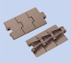
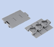
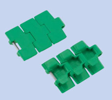
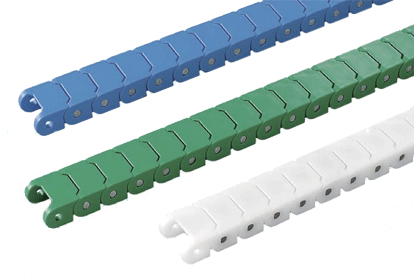
[Plastic modular chain] By combining plastic modular links with a chain structure in a brick-like configuration, a wide belt-like conveying surface is created, and reliable drive is achieved through the meshing of the chain and sprockets. You can choose from "closed type," "open type," "net type," etc. depending on the application and shape of the transported object. In addition, the lineup also includes "magnetic type," "rubber type," and "flight type" that are suitable for inclined transport. The conveying surface can be as wide as 50 mm, allowing for conveying over a wider surface than Plastic top chain or Plastic block chain. [Main uses] Ideal for transporting wide or large quantities of products at once, and for transporting heavy items.
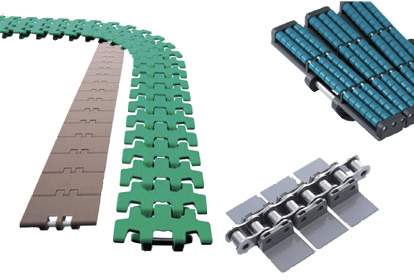
[Plastic top chain] The top plate and chain are molded as a single piece from plastic and connected with a joint pin. We also offer a lineup of models where only the top plate is made of plastic and the chain is made of steel.We also have models with freely rotating rollers attached to the plate, which reduces line pressure during accumulation. The top plate width can be selected from 42.0 to 304.8 mm to suit the items being transported. [Main uses] Ideal for loading and transporting plates one by one
[Plastic block chain] It has a simple structure with block-shaped links connected by joint pins. It uses a smaller chain pitch (9.525 to 25.4 mm) than Plastic top chain, allowing the outer diameter of the sprocket to be smaller. The link width is small, ranging from 13 to 63 mm, allowing for installation in small spaces. [Main uses]
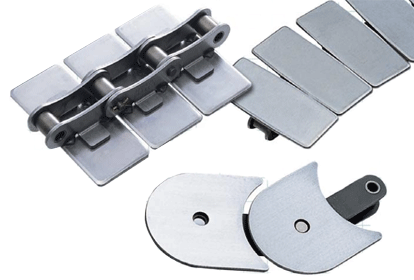
[Stainless steel Top chain] Top chain uses stainless steel for its main parts, which has excellent corrosion resistance. There are types in which the top plate is made integral with the chain, and types in which the two are joined together. Generally, Maximum allowable load is greater than that of Plastic top chain. [Main uses]
|
|||||||||||||||||||||||||||||||||||||||||||||||||||||||||||||||||||||||||||||||||||||||||||||||||||||||||||||||||||||||||||||||||||||||||||||||||||||||||||||||||||||||||||||||||||||||||||||||||||||||||||||||||||||||||||||||||||||||||||||||||||||||||||||||||||||||||||||||||||||||||||||||||||||||||||||||||||||||||||||||||||||||||||||||||||||||||||||||||||||||||||||||||||||||||||||||||||||||||||||||||||||||||||||||||||||||||||||||||||||||||||||||||||||||||||||||||||||||||||||||||||||||||||||||||||||||||||||||||||||||||||||||||||||||||||||||||||||||||||||||||||||||||||||||||||||||||||||||||||||||||||||||||||||||||||||||||||||||||||||||||||||||||||||||||||||||||||||||||||||||||||||||||||||||||||||||||||||||||||||||||||||||||||||||||||||||||||||||||||
| Q3 | How do I choose Top chain specifications (material)? | |||||||||||||||||||||||||||||||||||||||||||||||||||||||||||||||||||||||||||||||||||||||||||||||||||||||||||||||||||||||||||||||||||||||||||||||||||||||||||||||||||||||||||||||||||||||||||||||||||||||||||||||||||||||||||||||||||||||||||||||||||||||||||||||||||||||||||||||||||||||||||||||||||||||||||||||||||||||||||||||||||||||||||||||||||||||||||||||||||||||||||||||||||||||||||||||||||||||||||||||||||||||||||||||||||||||||||||||||||||||||||||||||||||||||||||||||||||||||||||||||||||||||||||||||||||||||||||||||||||||||||||||||||||||||||||||||||||||||||||||||||||||||||||||||||||||||||||||||||||||||||||||||||||||||||||||||||||||||||||||||||||||||||||||||||||||||||||||||||||||||||||||||||||||||||||||||||||||||||||||||||||||||||||||||||||||||||||||||||
| A3 |
Please check the link below for how to select specifications and the application table for each specification. Back to Questions |
|||||||||||||||||||||||||||||||||||||||||||||||||||||||||||||||||||||||||||||||||||||||||||||||||||||||||||||||||||||||||||||||||||||||||||||||||||||||||||||||||||||||||||||||||||||||||||||||||||||||||||||||||||||||||||||||||||||||||||||||||||||||||||||||||||||||||||||||||||||||||||||||||||||||||||||||||||||||||||||||||||||||||||||||||||||||||||||||||||||||||||||||||||||||||||||||||||||||||||||||||||||||||||||||||||||||||||||||||||||||||||||||||||||||||||||||||||||||||||||||||||||||||||||||||||||||||||||||||||||||||||||||||||||||||||||||||||||||||||||||||||||||||||||||||||||||||||||||||||||||||||||||||||||||||||||||||||||||||||||||||||||||||||||||||||||||||||||||||||||||||||||||||||||||||||||||||||||||||||||||||||||||||||||||||||||||||||||||||||
| Q4 | What is the difference between stainless steel pins and plastic pins? | |||||||||||||||||||||||||||||||||||||||||||||||||||||||||||||||||||||||||||||||||||||||||||||||||||||||||||||||||||||||||||||||||||||||||||||||||||||||||||||||||||||||||||||||||||||||||||||||||||||||||||||||||||||||||||||||||||||||||||||||||||||||||||||||||||||||||||||||||||||||||||||||||||||||||||||||||||||||||||||||||||||||||||||||||||||||||||||||||||||||||||||||||||||||||||||||||||||||||||||||||||||||||||||||||||||||||||||||||||||||||||||||||||||||||||||||||||||||||||||||||||||||||||||||||||||||||||||||||||||||||||||||||||||||||||||||||||||||||||||||||||||||||||||||||||||||||||||||||||||||||||||||||||||||||||||||||||||||||||||||||||||||||||||||||||||||||||||||||||||||||||||||||||||||||||||||||||||||||||||||||||||||||||||||||||||||||||||||||||
| A4 |
Plastic pin specifications are lightweight and very easy to handle, and are the mainstream for Plastic modular chain and Plastic top chain, if the chain is only exposed to water (which has adhered to the transported items from the previous process), stainless steel pin specifications may have a short lifespan due to the effects of water, so plastic pin specifications are recommended. Stainless steel pin specifications are the mainstream for Plastic block chain, but depending on the product, allowable tension may be greater than that of plastic pin specifications. Also, stainless steel pin specifications are recommended for products that are subject to impact. Plastic pin specification
Approximately the same allowable tension as stainless steel pins (80-100%) Long life: Tsubaki's unique combination of materials provides excellent wear resistance between the pin and bushing under a variety of conditions, including dry, soapy water, and water. It is particularly effective with water lubrication. Lightweight: 75-85% lighter than Top chain with stainless steel pins. Easy to handle, reduces power requirements and noise. Easy to dispose of: The entire chain is made of engineering plastic, so it can be disposed of as is. Conforms to the Food Sanitation Act: Both the links and pins are made from materials that conform to the Food Sanitation Act. Notes: 1. Please refer to the catalog technical notes, handling of Top chain, precautions for use of plastic pin types, and disassembly and connection.
|
|||||||||||||||||||||||||||||||||||||||||||||||||||||||||||||||||||||||||||||||||||||||||||||||||||||||||||||||||||||||||||||||||||||||||||||||||||||||||||||||||||||||||||||||||||||||||||||||||||||||||||||||||||||||||||||||||||||||||||||||||||||||||||||||||||||||||||||||||||||||||||||||||||||||||||||||||||||||||||||||||||||||||||||||||||||||||||||||||||||||||||||||||||||||||||||||||||||||||||||||||||||||||||||||||||||||||||||||||||||||||||||||||||||||||||||||||||||||||||||||||||||||||||||||||||||||||||||||||||||||||||||||||||||||||||||||||||||||||||||||||||||||||||||||||||||||||||||||||||||||||||||||||||||||||||||||||||||||||||||||||||||||||||||||||||||||||||||||||||||||||||||||||||||||||||||||||||||||||||||||||||||||||||||||||||||||||||||||||||
| Q5 | How to choose the rail material? | |||||||||||||||||||||||||||||||||||||||||||||||||||||||||||||||||||||||||||||||||||||||||||||||||||||||||||||||||||||||||||||||||||||||||||||||||||||||||||||||||||||||||||||||||||||||||||||||||||||||||||||||||||||||||||||||||||||||||||||||||||||||||||||||||||||||||||||||||||||||||||||||||||||||||||||||||||||||||||||||||||||||||||||||||||||||||||||||||||||||||||||||||||||||||||||||||||||||||||||||||||||||||||||||||||||||||||||||||||||||||||||||||||||||||||||||||||||||||||||||||||||||||||||||||||||||||||||||||||||||||||||||||||||||||||||||||||||||||||||||||||||||||||||||||||||||||||||||||||||||||||||||||||||||||||||||||||||||||||||||||||||||||||||||||||||||||||||||||||||||||||||||||||||||||||||||||||||||||||||||||||||||||||||||||||||||||||||||||||
| A5 |
When designing a plastic chain, a rail is generally installed to support the chain. The material of this rail is selected depending on the application and purpose. General-purpose use
Ultra-high molecular weight polyethylene rails (Plastic rail, P-rail) are often used. Recommended for lubricated conditions. When you want to reduce the generation of Wear debris
We recommend using PLF or M rails. Stainless steel (polished) or metal rails (hard chromium plated and buffed) will also reduce the generation of Wear debris. *M rails are designed for dry conditions only. Do not use in places where they are subject to lubrication or water. * Wear debris generated by metal rails such as stainless steel are black and contain metal particles. Click here for details on the features of each rail When used in a high temperature environment
We recommend using metal rails that are polished or have a hard chrome plating and buff finish. When used at high temperatures We recommend using stainless steel (cold rolled material) for the rail material. When fixing the rails, fix only one end, taking thermal expansion into consideration. Also, take thermal expansion into consideration when leaving gaps between rails. (Reference: The linear expansion coefficient of SUS304 is 1.8 x10 -5 mm/mm/℃) Standard steel sprockets can be used when the ambient temperature is below 150°C. When using multiple strand chains, the gap between the chains should be the following dimensions.
Take-up is necessary to absorb thermal expansion of the chain. Always adjust the take-up after raising the temperature to the operating temperature. When lowering the temperature, be sure to loosen the take-up first. Black Wear debris will be generated, so clean it regularly. When starting up, use a slow start (using inverter control, etc.), and when stopping, use a slow stop.
Note)
Note: Operating temperature range
|
|||||||||||||||||||||||||||||||||||||||||||||||||||||||||||||||||||||||||||||||||||||||||||||||||||||||||||||||||||||||||||||||||||||||||||||||||||||||||||||||||||||||||||||||||||||||||||||||||||||||||||||||||||||||||||||||||||||||||||||||||||||||||||||||||||||||||||||||||||||||||||||||||||||||||||||||||||||||||||||||||||||||||||||||||||||||||||||||||||||||||||||||||||||||||||||||||||||||||||||||||||||||||||||||||||||||||||||||||||||||||||||||||||||||||||||||||||||||||||||||||||||||||||||||||||||||||||||||||||||||||||||||||||||||||||||||||||||||||||||||||||||||||||||||||||||||||||||||||||||||||||||||||||||||||||||||||||||||||||||||||||||||||||||||||||||||||||||||||||||||||||||||||||||||||||||||||||||||||||||||||||||||||||||||||||||||||||||||||||
| Q6 | How to install straight rails? | |||||||||||||||||||||||||||||||||||||||||||||||||||||||||||||||||||||||||||||||||||||||||||||||||||||||||||||||||||||||||||||||||||||||||||||||||||||||||||||||||||||||||||||||||||||||||||||||||||||||||||||||||||||||||||||||||||||||||||||||||||||||||||||||||||||||||||||||||||||||||||||||||||||||||||||||||||||||||||||||||||||||||||||||||||||||||||||||||||||||||||||||||||||||||||||||||||||||||||||||||||||||||||||||||||||||||||||||||||||||||||||||||||||||||||||||||||||||||||||||||||||||||||||||||||||||||||||||||||||||||||||||||||||||||||||||||||||||||||||||||||||||||||||||||||||||||||||||||||||||||||||||||||||||||||||||||||||||||||||||||||||||||||||||||||||||||||||||||||||||||||||||||||||||||||||||||||||||||||||||||||||||||||||||||||||||||||||||||||
| A6 |
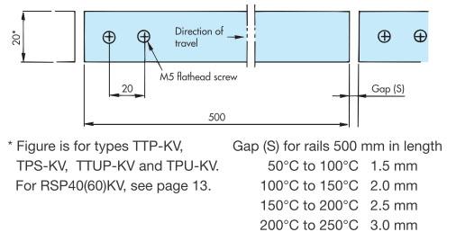
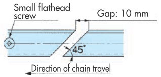
When using plastic rails (Plastic rail, PLF rails, M rails) for straight tracks, please leave a gap between the rails to allow for thermal expansion. Also, please secure the rails with a screw at one point on each end. Concave and convex (PR, PH), flat rail
Gap between uneven rails: 3 to 5 mm *Linear expansion coefficient Plastic rail (P-rail) / (PLF-rail) 20 x 10-5 mm/mm/℃" M rail 9×10⁻⁵ mm/mm/℃ Note)
Long straight type (Z-type, T-type, L-type, flat extrusion rails, etc.)...For long conveyor conveyor length
Long straight type (Z-type, T-type, L-type, flat extrusion rails, etc.)...When the conveyor conveyor length is short
Back to Questions |
|||||||||||||||||||||||||||||||||||||||||||||||||||||||||||||||||||||||||||||||||||||||||||||||||||||||||||||||||||||||||||||||||||||||||||||||||||||||||||||||||||||||||||||||||||||||||||||||||||||||||||||||||||||||||||||||||||||||||||||||||||||||||||||||||||||||||||||||||||||||||||||||||||||||||||||||||||||||||||||||||||||||||||||||||||||||||||||||||||||||||||||||||||||||||||||||||||||||||||||||||||||||||||||||||||||||||||||||||||||||||||||||||||||||||||||||||||||||||||||||||||||||||||||||||||||||||||||||||||||||||||||||||||||||||||||||||||||||||||||||||||||||||||||||||||||||||||||||||||||||||||||||||||||||||||||||||||||||||||||||||||||||||||||||||||||||||||||||||||||||||||||||||||||||||||||||||||||||||||||||||||||||||||||||||||||||||||||||||||
| Q7 | What are some examples of the Ultra Low Friction / Anti-Wear (ALF) specification? | |||||||||||||||||||||||||||||||||||||||||||||||||||||||||||||||||||||||||||||||||||||||||||||||||||||||||||||||||||||||||||||||||||||||||||||||||||||||||||||||||||||||||||||||||||||||||||||||||||||||||||||||||||||||||||||||||||||||||||||||||||||||||||||||||||||||||||||||||||||||||||||||||||||||||||||||||||||||||||||||||||||||||||||||||||||||||||||||||||||||||||||||||||||||||||||||||||||||||||||||||||||||||||||||||||||||||||||||||||||||||||||||||||||||||||||||||||||||||||||||||||||||||||||||||||||||||||||||||||||||||||||||||||||||||||||||||||||||||||||||||||||||||||||||||||||||||||||||||||||||||||||||||||||||||||||||||||||||||||||||||||||||||||||||||||||||||||||||||||||||||||||||||||||||||||||||||||||||||||||||||||||||||||||||||||||||||||||||||||
| A7 |
There are many examples of successful applications, but here are some representative examples.
|
|||||||||||||||||||||||||||||||||||||||||||||||||||||||||||||||||||||||||||||||||||||||||||||||||||||||||||||||||||||||||||||||||||||||||||||||||||||||||||||||||||||||||||||||||||||||||||||||||||||||||||||||||||||||||||||||||||||||||||||||||||||||||||||||||||||||||||||||||||||||||||||||||||||||||||||||||||||||||||||||||||||||||||||||||||||||||||||||||||||||||||||||||||||||||||||||||||||||||||||||||||||||||||||||||||||||||||||||||||||||||||||||||||||||||||||||||||||||||||||||||||||||||||||||||||||||||||||||||||||||||||||||||||||||||||||||||||||||||||||||||||||||||||||||||||||||||||||||||||||||||||||||||||||||||||||||||||||||||||||||||||||||||||||||||||||||||||||||||||||||||||||||||||||||||||||||||||||||||||||||||||||||||||||||||||||||||||||||||||
| Q8 | What is the corrosion resistance of the material used for Top chain? | |||||||||||||||||||||||||||||||||||||||||||||||||||||||||||||||||||||||||||||||||||||||||||||||||||||||||||||||||||||||||||||||||||||||||||||||||||||||||||||||||||||||||||||||||||||||||||||||||||||||||||||||||||||||||||||||||||||||||||||||||||||||||||||||||||||||||||||||||||||||||||||||||||||||||||||||||||||||||||||||||||||||||||||||||||||||||||||||||||||||||||||||||||||||||||||||||||||||||||||||||||||||||||||||||||||||||||||||||||||||||||||||||||||||||||||||||||||||||||||||||||||||||||||||||||||||||||||||||||||||||||||||||||||||||||||||||||||||||||||||||||||||||||||||||||||||||||||||||||||||||||||||||||||||||||||||||||||||||||||||||||||||||||||||||||||||||||||||||||||||||||||||||||||||||||||||||||||||||||||||||||||||||||||||||||||||||||||||||||
| A8 |
When selecting a chain, check the table below to see if the material is sufficient. This corrosion resistance can also be used to check the rail material to be used with Top chain. Please note that this table shows the results in an atmosphere of 20°C and does not represent the degree of guarantee. When actually using the product, please comprehensively consider the temperature, operating conditions, etc. The table below lists the materials (specifications) of the top plate and chain components individually, so please check them in combination. Reagents without a concentration indication are saturated or 100% solutions. Please note that the conditions will change if you mix solutions. [Corrosion resistance to various liquids]
Note)
|
|||||||||||||||||||||||||||||||||||||||||||||||||||||||||||||||||||||||||||||||||||||||||||||||||||||||||||||||||||||||||||||||||||||||||||||||||||||||||||||||||||||||||||||||||||||||||||||||||||||||||||||||||||||||||||||||||||||||||||||||||||||||||||||||||||||||||||||||||||||||||||||||||||||||||||||||||||||||||||||||||||||||||||||||||||||||||||||||||||||||||||||||||||||||||||||||||||||||||||||||||||||||||||||||||||||||||||||||||||||||||||||||||||||||||||||||||||||||||||||||||||||||||||||||||||||||||||||||||||||||||||||||||||||||||||||||||||||||||||||||||||||||||||||||||||||||||||||||||||||||||||||||||||||||||||||||||||||||||||||||||||||||||||||||||||||||||||||||||||||||||||||||||||||||||||||||||||||||||||||||||||||||||||||||||||||||||||||||||||
| Q9 | What is the conveyor design for Plastic top chain and Plastic block chain? | |||||||||||||||||||||||||||||||||||||||||||||||||||||||||||||||||||||||||||||||||||||||||||||||||||||||||||||||||||||||||||||||||||||||||||||||||||||||||||||||||||||||||||||||||||||||||||||||||||||||||||||||||||||||||||||||||||||||||||||||||||||||||||||||||||||||||||||||||||||||||||||||||||||||||||||||||||||||||||||||||||||||||||||||||||||||||||||||||||||||||||||||||||||||||||||||||||||||||||||||||||||||||||||||||||||||||||||||||||||||||||||||||||||||||||||||||||||||||||||||||||||||||||||||||||||||||||||||||||||||||||||||||||||||||||||||||||||||||||||||||||||||||||||||||||||||||||||||||||||||||||||||||||||||||||||||||||||||||||||||||||||||||||||||||||||||||||||||||||||||||||||||||||||||||||||||||||||||||||||||||||||||||||||||||||||||||||||||||||
| A9 |
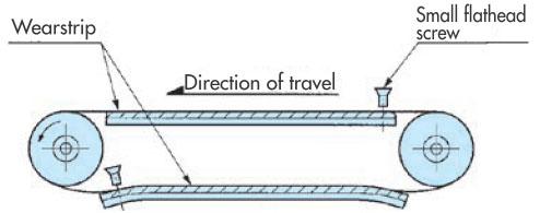
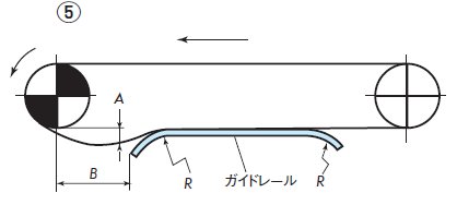
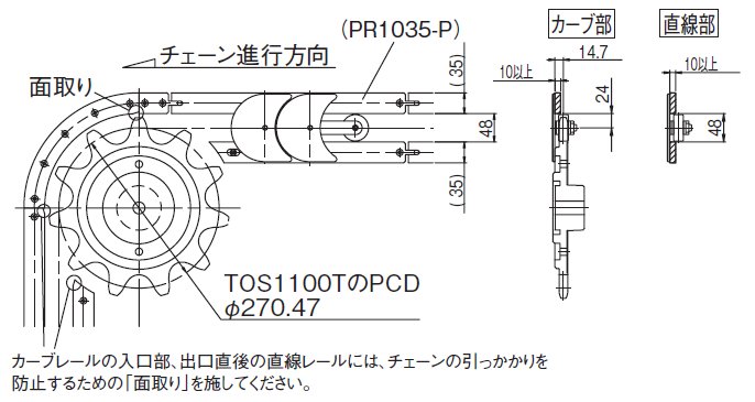
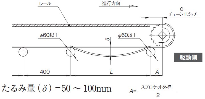
With plastic chains, the chain should generally be supported by a rail on the transport side, and there should be some slack in the chain on the return side. Slack below the drive sprocket is particularly important. A span of 500 to 900 mm and 50 to 100 mm of slack (during operation) should be maintained. If the slack is outside this range, the chain may skip teeth. The layout of guide channel will vary depending on the installation space, but an example is shown in the diagram below. For the layout on the return side, please refer to Q.8.
Chain slack The intervals between the return rollers that receive return-way chain should be 500 to 900mm, with 50 to 100mm of slack in the chain between the return rollers. This slack prevents tooth skipping. If the interval or amount of slack is outside this range, tooth skipping may occur. Meshing angle The "engagement angle" between the drive sprocket and chain should be 150° or more. Rail End Leave a distance of one chain pitch from the drive and driven rail ends to the center of each shaft. Also, bend or chamfer the driven rail end to prevent the chain from getting caught on the rail. Height of conveying side wearstrip Please refer to the catalog technical notes, conveyor design, and rail installation on the drive and driven sides. Back to Questions |
|||||||||||||||||||||||||||||||||||||||||||||||||||||||||||||||||||||||||||||||||||||||||||||||||||||||||||||||||||||||||||||||||||||||||||||||||||||||||||||||||||||||||||||||||||||||||||||||||||||||||||||||||||||||||||||||||||||||||||||||||||||||||||||||||||||||||||||||||||||||||||||||||||||||||||||||||||||||||||||||||||||||||||||||||||||||||||||||||||||||||||||||||||||||||||||||||||||||||||||||||||||||||||||||||||||||||||||||||||||||||||||||||||||||||||||||||||||||||||||||||||||||||||||||||||||||||||||||||||||||||||||||||||||||||||||||||||||||||||||||||||||||||||||||||||||||||||||||||||||||||||||||||||||||||||||||||||||||||||||||||||||||||||||||||||||||||||||||||||||||||||||||||||||||||||||||||||||||||||||||||||||||||||||||||||||||||||||||||||
| Q10 | Layout of the return side of Top chain and Plastic block chain | |||||||||||||||||||||||||||||||||||||||||||||||||||||||||||||||||||||||||||||||||||||||||||||||||||||||||||||||||||||||||||||||||||||||||||||||||||||||||||||||||||||||||||||||||||||||||||||||||||||||||||||||||||||||||||||||||||||||||||||||||||||||||||||||||||||||||||||||||||||||||||||||||||||||||||||||||||||||||||||||||||||||||||||||||||||||||||||||||||||||||||||||||||||||||||||||||||||||||||||||||||||||||||||||||||||||||||||||||||||||||||||||||||||||||||||||||||||||||||||||||||||||||||||||||||||||||||||||||||||||||||||||||||||||||||||||||||||||||||||||||||||||||||||||||||||||||||||||||||||||||||||||||||||||||||||||||||||||||||||||||||||||||||||||||||||||||||||||||||||||||||||||||||||||||||||||||||||||||||||||||||||||||||||||||||||||||||||||||||
| A10 |
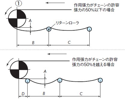
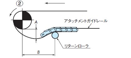
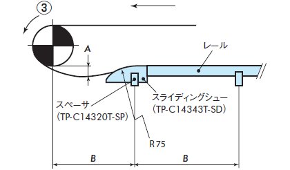
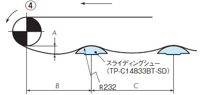
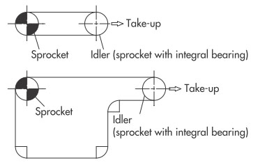
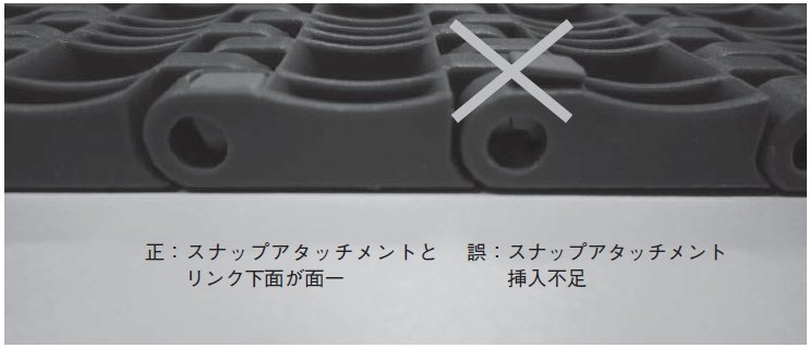
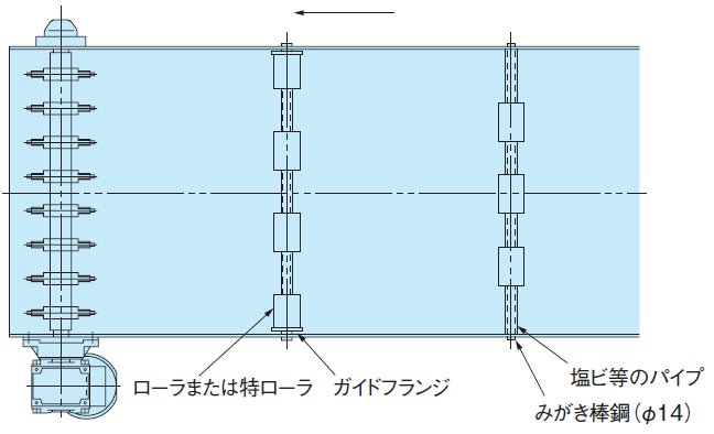
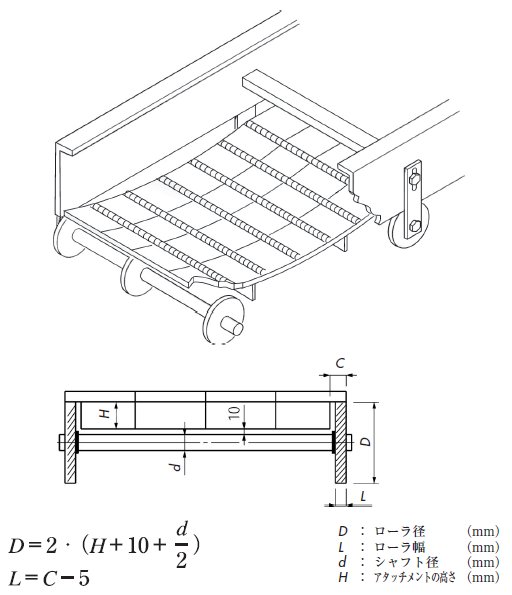
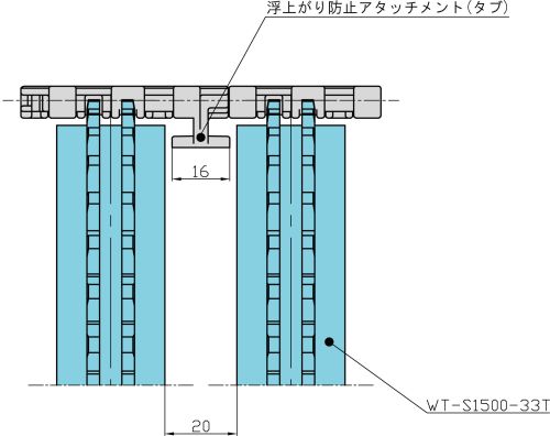
The most common layout is the recommended method of supporting the chain with return rollers. This method is recommended because it allows for appropriate chain slack and can absorb chain elongation. Furthermore, if a chain with float-preventive tabs is used, a method using the sliding attachment can also be applied. However, please consider installing a mechanism (tensioner, etc.) to absorb chain elongation. The layout on the return side will vary depending on the type of chain, type and format of the transported material, route, etc., but a typical layout is shown below.
|
|||||||||||||||||||||||||||||||||||||||||||||||||||||||||||||||||||||||||||||||||||||||||||||||||||||||||||||||||||||||||||||||||||||||||||||||||||||||||||||||||||||||||||||||||||||||||||||||||||||||||||||||||||||||||||||||||||||||||||||||||||||||||||||||||||||||||||||||||||||||||||||||||||||||||||||||||||||||||||||||||||||||||||||||||||||||||||||||||||||||||||||||||||||||||||||||||||||||||||||||||||||||||||||||||||||||||||||||||||||||||||||||||||||||||||||||||||||||||||||||||||||||||||||||||||||||||||||||||||||||||||||||||||||||||||||||||||||||||||||||||||||||||||||||||||||||||||||||||||||||||||||||||||||||||||||||||||||||||||||||||||||||||||||||||||||||||||||||||||||||||||||||||||||||||||||||||||||||||||||||||||||||||||||||||||||||||||||||||||
| Q11 | Conveyors using corner discs | |||||||||||||||||||||||||||||||||||||||||||||||||||||||||||||||||||||||||||||||||||||||||||||||||||||||||||||||||||||||||||||||||||||||||||||||||||||||||||||||||||||||||||||||||||||||||||||||||||||||||||||||||||||||||||||||||||||||||||||||||||||||||||||||||||||||||||||||||||||||||||||||||||||||||||||||||||||||||||||||||||||||||||||||||||||||||||||||||||||||||||||||||||||||||||||||||||||||||||||||||||||||||||||||||||||||||||||||||||||||||||||||||||||||||||||||||||||||||||||||||||||||||||||||||||||||||||||||||||||||||||||||||||||||||||||||||||||||||||||||||||||||||||||||||||||||||||||||||||||||||||||||||||||||||||||||||||||||||||||||||||||||||||||||||||||||||||||||||||||||||||||||||||||||||||||||||||||||||||||||||||||||||||||||||||||||||||||||||||
| A11 |
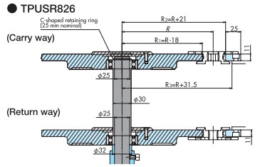
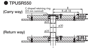
For chains with a small bending radius (minimum bending radius (R190 or less)), corner discs should be installed when manufacturing a conveyor with a small bending radius. Install the shaft at the center of the bending radius and install corner discs on the conveying side and return side. Curved section using corner discs for TPUSR chains
(Explanation of symbols)
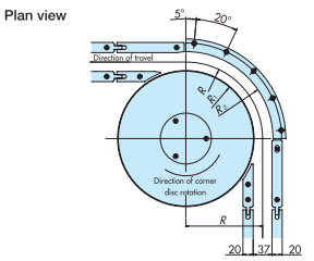
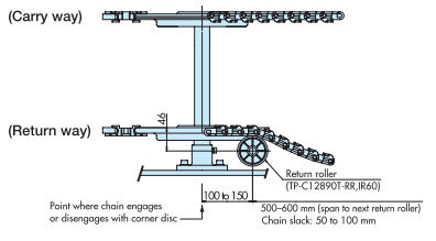
For conveyors that use return rollers to support the return straight section, be sure to install return rollers at the entrance and exit of corners to provide guidance, as shown in the diagram below. Note: It is recommended to use in a dry environment.
|
|||||||||||||||||||||||||||||||||||||||||||||||||||||||||||||||||||||||||||||||||||||||||||||||||||||||||||||||||||||||||||||||||||||||||||||||||||||||||||||||||||||||||||||||||||||||||||||||||||||||||||||||||||||||||||||||||||||||||||||||||||||||||||||||||||||||||||||||||||||||||||||||||||||||||||||||||||||||||||||||||||||||||||||||||||||||||||||||||||||||||||||||||||||||||||||||||||||||||||||||||||||||||||||||||||||||||||||||||||||||||||||||||||||||||||||||||||||||||||||||||||||||||||||||||||||||||||||||||||||||||||||||||||||||||||||||||||||||||||||||||||||||||||||||||||||||||||||||||||||||||||||||||||||||||||||||||||||||||||||||||||||||||||||||||||||||||||||||||||||||||||||||||||||||||||||||||||||||||||||||||||||||||||||||||||||||||||||||||||
| Q12 | What is the conveyor design for Plastic Crescent Chain? | |||||||||||||||||||||||||||||||||||||||||||||||||||||||||||||||||||||||||||||||||||||||||||||||||||||||||||||||||||||||||||||||||||||||||||||||||||||||||||||||||||||||||||||||||||||||||||||||||||||||||||||||||||||||||||||||||||||||||||||||||||||||||||||||||||||||||||||||||||||||||||||||||||||||||||||||||||||||||||||||||||||||||||||||||||||||||||||||||||||||||||||||||||||||||||||||||||||||||||||||||||||||||||||||||||||||||||||||||||||||||||||||||||||||||||||||||||||||||||||||||||||||||||||||||||||||||||||||||||||||||||||||||||||||||||||||||||||||||||||||||||||||||||||||||||||||||||||||||||||||||||||||||||||||||||||||||||||||||||||||||||||||||||||||||||||||||||||||||||||||||||||||||||||||||||||||||||||||||||||||||||||||||||||||||||||||||||||||||||
| A12 |
Plastic Crescent Chain is a chain that can be used for horizontal conveyance. For TORP (with rollers) types, guide the corners with sprockets or rails. For TOSP (without rollers) types, use sprockets at the corners. Furthermore, for horizontal conveyors, a take-up mechanism is required to absorb chain elongation due to wear and temperature changes. Failure to do so may result in tooth skipping and other problems with conveyance. Guide channel placement This may vary depending on the space available, but please refer to the example below. Rail installation example ①…TOSP1143 + corner sprockets used
Rail installation example ②…When using TORP1143 + corner sprockets
Rail installation example 3…TORP1143 + curved corner rails
Conveyor layout considerations Be sure to install a take-up mechanism to absorb stretching due to wear on the conveyor and temperature changes. See the example below.
|
|||||||||||||||||||||||||||||||||||||||||||||||||||||||||||||||||||||||||||||||||||||||||||||||||||||||||||||||||||||||||||||||||||||||||||||||||||||||||||||||||||||||||||||||||||||||||||||||||||||||||||||||||||||||||||||||||||||||||||||||||||||||||||||||||||||||||||||||||||||||||||||||||||||||||||||||||||||||||||||||||||||||||||||||||||||||||||||||||||||||||||||||||||||||||||||||||||||||||||||||||||||||||||||||||||||||||||||||||||||||||||||||||||||||||||||||||||||||||||||||||||||||||||||||||||||||||||||||||||||||||||||||||||||||||||||||||||||||||||||||||||||||||||||||||||||||||||||||||||||||||||||||||||||||||||||||||||||||||||||||||||||||||||||||||||||||||||||||||||||||||||||||||||||||||||||||||||||||||||||||||||||||||||||||||||||||||||||||||||
| Q13 | How do I disassemble and assemble Plastic top chain and Plastic block chain? | |||||||||||||||||||||||||||||||||||||||||||||||||||||||||||||||||||||||||||||||||||||||||||||||||||||||||||||||||||||||||||||||||||||||||||||||||||||||||||||||||||||||||||||||||||||||||||||||||||||||||||||||||||||||||||||||||||||||||||||||||||||||||||||||||||||||||||||||||||||||||||||||||||||||||||||||||||||||||||||||||||||||||||||||||||||||||||||||||||||||||||||||||||||||||||||||||||||||||||||||||||||||||||||||||||||||||||||||||||||||||||||||||||||||||||||||||||||||||||||||||||||||||||||||||||||||||||||||||||||||||||||||||||||||||||||||||||||||||||||||||||||||||||||||||||||||||||||||||||||||||||||||||||||||||||||||||||||||||||||||||||||||||||||||||||||||||||||||||||||||||||||||||||||||||||||||||||||||||||||||||||||||||||||||||||||||||||||||||||
| A13 |
The joint pins differ depending on the type. Please use a punch and hammer to disassemble and cut/splice according to the shape of the joint pin. Only Plastic Crescent Chain have a unique structure. Please see below. The joint pin is a D-pin type (excluding TPUN555) The chain can be disassembled from any point, and the pins can be inserted and removed from either the left or right side.
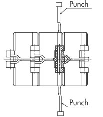
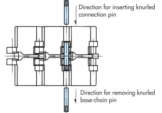
The joint pin is a knurled pin type When disassembling, use a punch on the end without knurling to remove the part. When reconnecting, use a punch on the end with knurling to reconnect the part.
TN、TNU、TRU、TP-1873G、TP-1873T、TP-1843G The pin and one side of the outer plate at the joint are loose-fitting. If you are disassembling the link at a location other than the joint, use a chain vise or similar tool to remove the pair of pins parallel to one another. Please note that links disassembled at locations other than the joint cannot be reused. The joint pin is a D-pin type (excluding TPUN555) The pin can be inserted in one direction. Plastic Crescent Chain
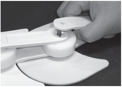
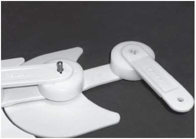
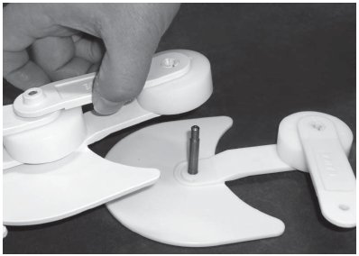
1. Remove the snap pin from the coupling pin and remove the offset link.
2. Rotate the offset link 90 degrees.
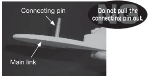
3. Remove the connecting pin along with the main link from the previous link.
Caution: When disassembling, do not remove the coupling pin from the main link. Back to Questions |
|||||||||||||||||||||||||||||||||||||||||||||||||||||||||||||||||||||||||||||||||||||||||||||||||||||||||||||||||||||||||||||||||||||||||||||||||||||||||||||||||||||||||||||||||||||||||||||||||||||||||||||||||||||||||||||||||||||||||||||||||||||||||||||||||||||||||||||||||||||||||||||||||||||||||||||||||||||||||||||||||||||||||||||||||||||||||||||||||||||||||||||||||||||||||||||||||||||||||||||||||||||||||||||||||||||||||||||||||||||||||||||||||||||||||||||||||||||||||||||||||||||||||||||||||||||||||||||||||||||||||||||||||||||||||||||||||||||||||||||||||||||||||||||||||||||||||||||||||||||||||||||||||||||||||||||||||||||||||||||||||||||||||||||||||||||||||||||||||||||||||||||||||||||||||||||||||||||||||||||||||||||||||||||||||||||||||||||||||||
| Q14 | What precautions should I take when using plastic pins on Plastic top chain and Plastic block chain? | |||||||||||||||||||||||||||||||||||||||||||||||||||||||||||||||||||||||||||||||||||||||||||||||||||||||||||||||||||||||||||||||||||||||||||||||||||||||||||||||||||||||||||||||||||||||||||||||||||||||||||||||||||||||||||||||||||||||||||||||||||||||||||||||||||||||||||||||||||||||||||||||||||||||||||||||||||||||||||||||||||||||||||||||||||||||||||||||||||||||||||||||||||||||||||||||||||||||||||||||||||||||||||||||||||||||||||||||||||||||||||||||||||||||||||||||||||||||||||||||||||||||||||||||||||||||||||||||||||||||||||||||||||||||||||||||||||||||||||||||||||||||||||||||||||||||||||||||||||||||||||||||||||||||||||||||||||||||||||||||||||||||||||||||||||||||||||||||||||||||||||||||||||||||||||||||||||||||||||||||||||||||||||||||||||||||||||||||||||
| A14 |
Do not reuse pins that have been removed, as this will reduce the interlocking force and cause problems with the pin coming out. The splicing pin is orange in color to distinguish it from the main pin (white). One splicing pin is included with each chain, so please use it when splicing. |
|||||||||||||||||||||||||||||||||||||||||||||||||||||||||||||||||||||||||||||||||||||||||||||||||||||||||||||||||||||||||||||||||||||||||||||||||||||||||||||||||||||||||||||||||||||||||||||||||||||||||||||||||||||||||||||||||||||||||||||||||||||||||||||||||||||||||||||||||||||||||||||||||||||||||||||||||||||||||||||||||||||||||||||||||||||||||||||||||||||||||||||||||||||||||||||||||||||||||||||||||||||||||||||||||||||||||||||||||||||||||||||||||||||||||||||||||||||||||||||||||||||||||||||||||||||||||||||||||||||||||||||||||||||||||||||||||||||||||||||||||||||||||||||||||||||||||||||||||||||||||||||||||||||||||||||||||||||||||||||||||||||||||||||||||||||||||||||||||||||||||||||||||||||||||||||||||||||||||||||||||||||||||||||||||||||||||||||||||||
| Q15 | Can Plastic top chain and Plastic block chain be operated forward and backward? | |||||||||||||||||||||||||||||||||||||||||||||||||||||||||||||||||||||||||||||||||||||||||||||||||||||||||||||||||||||||||||||||||||||||||||||||||||||||||||||||||||||||||||||||||||||||||||||||||||||||||||||||||||||||||||||||||||||||||||||||||||||||||||||||||||||||||||||||||||||||||||||||||||||||||||||||||||||||||||||||||||||||||||||||||||||||||||||||||||||||||||||||||||||||||||||||||||||||||||||||||||||||||||||||||||||||||||||||||||||||||||||||||||||||||||||||||||||||||||||||||||||||||||||||||||||||||||||||||||||||||||||||||||||||||||||||||||||||||||||||||||||||||||||||||||||||||||||||||||||||||||||||||||||||||||||||||||||||||||||||||||||||||||||||||||||||||||||||||||||||||||||||||||||||||||||||||||||||||||||||||||||||||||||||||||||||||||||||||||
| A15 |
Since the direction of travel of Plastic top chain and Plastic block chain is fixed, forward and reverse operation is not recommended. If forward and reverse operation is required, please consider using Plastic modular chain. Back to Questions |
|||||||||||||||||||||||||||||||||||||||||||||||||||||||||||||||||||||||||||||||||||||||||||||||||||||||||||||||||||||||||||||||||||||||||||||||||||||||||||||||||||||||||||||||||||||||||||||||||||||||||||||||||||||||||||||||||||||||||||||||||||||||||||||||||||||||||||||||||||||||||||||||||||||||||||||||||||||||||||||||||||||||||||||||||||||||||||||||||||||||||||||||||||||||||||||||||||||||||||||||||||||||||||||||||||||||||||||||||||||||||||||||||||||||||||||||||||||||||||||||||||||||||||||||||||||||||||||||||||||||||||||||||||||||||||||||||||||||||||||||||||||||||||||||||||||||||||||||||||||||||||||||||||||||||||||||||||||||||||||||||||||||||||||||||||||||||||||||||||||||||||||||||||||||||||||||||||||||||||||||||||||||||||||||||||||||||||||||||||
| Q16 | How should straight running TTP, TPF, TPS, and TPH be used? | |||||||||||||||||||||||||||||||||||||||||||||||||||||||||||||||||||||||||||||||||||||||||||||||||||||||||||||||||||||||||||||||||||||||||||||||||||||||||||||||||||||||||||||||||||||||||||||||||||||||||||||||||||||||||||||||||||||||||||||||||||||||||||||||||||||||||||||||||||||||||||||||||||||||||||||||||||||||||||||||||||||||||||||||||||||||||||||||||||||||||||||||||||||||||||||||||||||||||||||||||||||||||||||||||||||||||||||||||||||||||||||||||||||||||||||||||||||||||||||||||||||||||||||||||||||||||||||||||||||||||||||||||||||||||||||||||||||||||||||||||||||||||||||||||||||||||||||||||||||||||||||||||||||||||||||||||||||||||||||||||||||||||||||||||||||||||||||||||||||||||||||||||||||||||||||||||||||||||||||||||||||||||||||||||||||||||||||||||||
| A16 |
Please see the table below for how to use TTP for straight running, TPF, TPS, and TPH.
|
|||||||||||||||||||||||||||||||||||||||||||||||||||||||||||||||||||||||||||||||||||||||||||||||||||||||||||||||||||||||||||||||||||||||||||||||||||||||||||||||||||||||||||||||||||||||||||||||||||||||||||||||||||||||||||||||||||||||||||||||||||||||||||||||||||||||||||||||||||||||||||||||||||||||||||||||||||||||||||||||||||||||||||||||||||||||||||||||||||||||||||||||||||||||||||||||||||||||||||||||||||||||||||||||||||||||||||||||||||||||||||||||||||||||||||||||||||||||||||||||||||||||||||||||||||||||||||||||||||||||||||||||||||||||||||||||||||||||||||||||||||||||||||||||||||||||||||||||||||||||||||||||||||||||||||||||||||||||||||||||||||||||||||||||||||||||||||||||||||||||||||||||||||||||||||||||||||||||||||||||||||||||||||||||||||||||||||||||||||
| Q17 | What is the difference between TTUP and TPU for curved transport? | |||||||||||||||||||||||||||||||||||||||||||||||||||||||||||||||||||||||||||||||||||||||||||||||||||||||||||||||||||||||||||||||||||||||||||||||||||||||||||||||||||||||||||||||||||||||||||||||||||||||||||||||||||||||||||||||||||||||||||||||||||||||||||||||||||||||||||||||||||||||||||||||||||||||||||||||||||||||||||||||||||||||||||||||||||||||||||||||||||||||||||||||||||||||||||||||||||||||||||||||||||||||||||||||||||||||||||||||||||||||||||||||||||||||||||||||||||||||||||||||||||||||||||||||||||||||||||||||||||||||||||||||||||||||||||||||||||||||||||||||||||||||||||||||||||||||||||||||||||||||||||||||||||||||||||||||||||||||||||||||||||||||||||||||||||||||||||||||||||||||||||||||||||||||||||||||||||||||||||||||||||||||||||||||||||||||||||||||||||
| A17 |
Please see the table below for the use of TTUP and TPU for curved transport.
|
|||||||||||||||||||||||||||||||||||||||||||||||||||||||||||||||||||||||||||||||||||||||||||||||||||||||||||||||||||||||||||||||||||||||||||||||||||||||||||||||||||||||||||||||||||||||||||||||||||||||||||||||||||||||||||||||||||||||||||||||||||||||||||||||||||||||||||||||||||||||||||||||||||||||||||||||||||||||||||||||||||||||||||||||||||||||||||||||||||||||||||||||||||||||||||||||||||||||||||||||||||||||||||||||||||||||||||||||||||||||||||||||||||||||||||||||||||||||||||||||||||||||||||||||||||||||||||||||||||||||||||||||||||||||||||||||||||||||||||||||||||||||||||||||||||||||||||||||||||||||||||||||||||||||||||||||||||||||||||||||||||||||||||||||||||||||||||||||||||||||||||||||||||||||||||||||||||||||||||||||||||||||||||||||||||||||||||||||||||
| Q18 | What are the uses of Plastic modular chain? | |||||||||||||||||||||||||||||||||||||||||||||||||||||||||||||||||||||||||||||||||||||||||||||||||||||||||||||||||||||||||||||||||||||||||||||||||||||||||||||||||||||||||||||||||||||||||||||||||||||||||||||||||||||||||||||||||||||||||||||||||||||||||||||||||||||||||||||||||||||||||||||||||||||||||||||||||||||||||||||||||||||||||||||||||||||||||||||||||||||||||||||||||||||||||||||||||||||||||||||||||||||||||||||||||||||||||||||||||||||||||||||||||||||||||||||||||||||||||||||||||||||||||||||||||||||||||||||||||||||||||||||||||||||||||||||||||||||||||||||||||||||||||||||||||||||||||||||||||||||||||||||||||||||||||||||||||||||||||||||||||||||||||||||||||||||||||||||||||||||||||||||||||||||||||||||||||||||||||||||||||||||||||||||||||||||||||||||||||||
| A18 |
If you want to minimize transfer gaps between conveyors, we recommend the WT1500 series, BTN5, BT6, BTC4-M, and TOD types, which have smaller chain pitches. For general-purpose applications, we recommend the BT8, WT2250, WT2706, WT3835, and WT300 series. For load-bearing applications or heavy object transport, we recommend the WT2500 series and BTH16. For eliminating gaps at transfer points, we recommend the WT1907, 3827, and 5707 series. For inclined transport of metal trays or parts (to prevent slippage), we recommend the BTM8H and BTM8H-M, which have built-in magnets. We also recommend the WT2525 for transporting cardboard sheets, etc. For inclined transport, we recommend the WT2250 series with flights or rubber. Back to Questions |
|||||||||||||||||||||||||||||||||||||||||||||||||||||||||||||||||||||||||||||||||||||||||||||||||||||||||||||||||||||||||||||||||||||||||||||||||||||||||||||||||||||||||||||||||||||||||||||||||||||||||||||||||||||||||||||||||||||||||||||||||||||||||||||||||||||||||||||||||||||||||||||||||||||||||||||||||||||||||||||||||||||||||||||||||||||||||||||||||||||||||||||||||||||||||||||||||||||||||||||||||||||||||||||||||||||||||||||||||||||||||||||||||||||||||||||||||||||||||||||||||||||||||||||||||||||||||||||||||||||||||||||||||||||||||||||||||||||||||||||||||||||||||||||||||||||||||||||||||||||||||||||||||||||||||||||||||||||||||||||||||||||||||||||||||||||||||||||||||||||||||||||||||||||||||||||||||||||||||||||||||||||||||||||||||||||||||||||||||||
| Q19 | How do I disassemble and assemble Plastic modular chain? | |||||||||||||||||||||||||||||||||||||||||||||||||||||||||||||||||||||||||||||||||||||||||||||||||||||||||||||||||||||||||||||||||||||||||||||||||||||||||||||||||||||||||||||||||||||||||||||||||||||||||||||||||||||||||||||||||||||||||||||||||||||||||||||||||||||||||||||||||||||||||||||||||||||||||||||||||||||||||||||||||||||||||||||||||||||||||||||||||||||||||||||||||||||||||||||||||||||||||||||||||||||||||||||||||||||||||||||||||||||||||||||||||||||||||||||||||||||||||||||||||||||||||||||||||||||||||||||||||||||||||||||||||||||||||||||||||||||||||||||||||||||||||||||||||||||||||||||||||||||||||||||||||||||||||||||||||||||||||||||||||||||||||||||||||||||||||||||||||||||||||||||||||||||||||||||||||||||||||||||||||||||||||||||||||||||||||||||||||||
| A19 |
The structure varies depending on the chain series, so please refer to the information below. ■Structure and disassembly/connection of BTN5, BT6, and BT8 series Structure of both ends of the chain To prevent the pins from coming loose at both ends of the chain, snap attachments are inserted from the back of the links (snap fit). 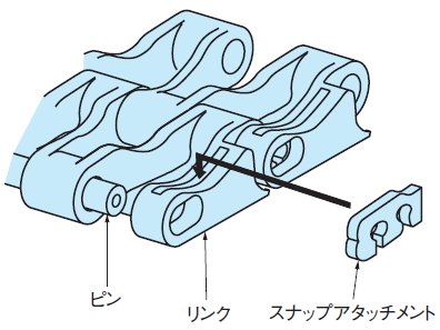 [Click to enlarge] Disassembly/connection instructions 1. Insert a thin flat-head screwdriver into the gap (approximately 1 mm) between the link hole and the snap attachment to remove the snap attachment. 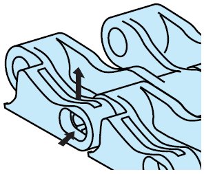 [Click to enlarge] ②Turn the screwdriver to bite into the center hole (φ1.0) of the pin, pull out the pin and disassemble the chain.  [Click to enlarge] 3. When connecting chains, pull the ends of the chain together and insert the pin into one end. Insert the snap attachment into the back of the chain. ■ Disassembly of the WT1500/3000 series 1. Insert a thin, flat-head screwdriver or similar tool between the plug on the side of the chain and the chain.  [Click to enlarge] ② Use a lever to remove the plug from the main body, being careful not to let the plug fly off. 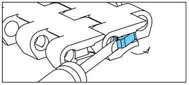 [Click to enlarge] ③ Rotate the screwdriver with the thread to insert it into the center hole (φ1) of the pin, then pull out the pin and disassemble the chain. 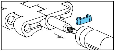 [Click to enlarge] ■ WT1500/3000 series connection ①When connecting chains, pull the chains together and insert a pin into one end. 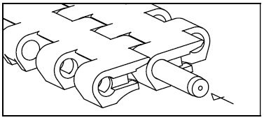 [Click to enlarge] ② Next, insert the plug to close the pin insertion section. When doing so, be careful of the orientation of the plug (so that the protrusion is in the pin hole) and press it in until you hear a click. 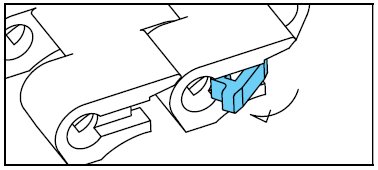 [Click to enlarge] 3) Check that the plug is installed correctly.  [Click to enlarge] Note: When connecting, please use the included or dedicated pins. ■ Disassembly of WT2500 series and BTM8H series 1. Insert a thin, flat-head screwdriver or similar tool into the plug hole on the side of the chain. 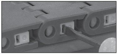 [Click to enlarge] ② Push the flathead screwdriver in the direction of the arrow and slide the plug. 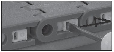 [Click to enlarge] ③ Rotate the screwdriver with the thread to insert it into the center hole (φ1) of the pin, then pull out the pin and disassemble the chain. 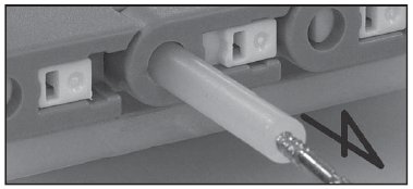 [Click to enlarge] *BTM8-M type is different. ■ WT2500 series and BTM8H series combination ①When connecting chains, pull the chains together and insert a pin into one end. 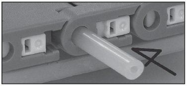 [Click to enlarge] ②Next, slide the plug to close the pin insertion section.  [Click to enlarge] *BTM8-M type is different. Note: When connecting, please use the included or dedicated pins. ■ Disassembly of the WT3800 series 1. Insert a thin, flat-head screwdriver or similar tool between the plug on the side of the chain and the chain. 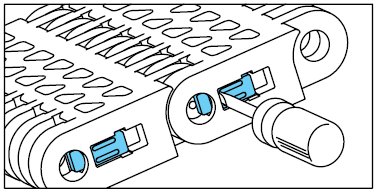 [Click to enlarge] ② Push the flathead screwdriver in the direction of the arrow and slide the plug. 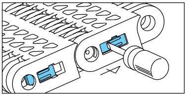 [Click to enlarge] ③ Rotate the screwdriver with the thread to insert it into the center hole (φ1) of the pin, then pull out the pin and disassemble the chain. 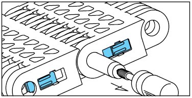 [Click to enlarge] ■ WT3800 series connection ①When connecting chains, pull the chains together and insert a pin into one end. 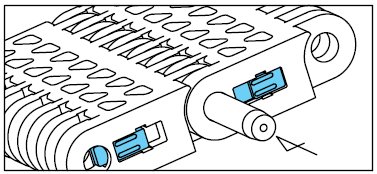 [Click to enlarge] ②Next, slide the plug to close the pin insertion section.  [Click to enlarge] Note: When connecting, please use the included or dedicated pins. ■ Disassembly and connection of BTC4-M and BTO8-M types ① During disassembly - Place a punch (φ2.5 or less) on the side of the D-pin on the D-hole side of the link and lightly hit it with a hammer to remove the pin. - Alternatively, you can remove the pin from the stopper side using a thin flat-head screwdriver. 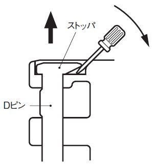 [Click to enlarge] ②When connecting - Please use the dedicated connecting D-pin (color: orange). - Check the insertion direction of the D-pin and insert the pin into the link. - Press the stopper side of the D-pin with your finger or lightly hit it with a hammer. ③When re-cutting and connecting - Do not cut and connect the connecting D-pin (color: orange) that has already been inserted. *About connecting D-pins ①When connecting, please use the dedicated connecting D-pin. ②The connecting D-pins are orange to distinguish them from the main pins (white). ③One connecting D-pin is included with each chain. ■WT2250, BTC8S series structure and disassembly/connection Structure of both ends of the chain To prevent the pins from coming loose at both ends of the chain, snap attachments are inserted from the back of the links (snap fit). 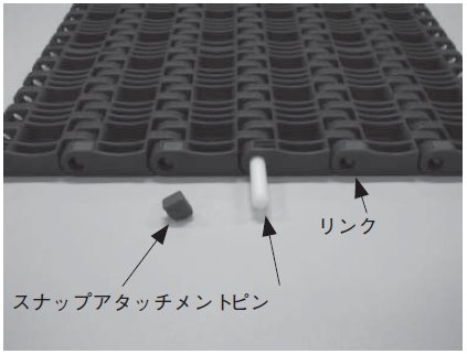 [Click to enlarge] Disassembly/connection instructions 1. Insert a thin flat-head screwdriver into the gap (approximately 1 mm) between the link hole and the snap attachment to remove the snap attachment. 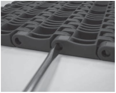 [Click to enlarge] ②Turn the screwdriver to bite into the center hole (φ1.0) of the pin, pull out the pin and disassemble the chain. 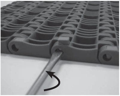 [Click to enlarge] 3. When connecting chains, pull the ends of the chain together and insert the pin into one end. Insert the snap attachment into the back of the chain. 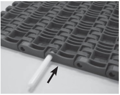 [Click to enlarge]
|
|||||||||||||||||||||||||||||||||||||||||||||||||||||||||||||||||||||||||||||||||||||||||||||||||||||||||||||||||||||||||||||||||||||||||||||||||||||||||||||||||||||||||||||||||||||||||||||||||||||||||||||||||||||||||||||||||||||||||||||||||||||||||||||||||||||||||||||||||||||||||||||||||||||||||||||||||||||||||||||||||||||||||||||||||||||||||||||||||||||||||||||||||||||||||||||||||||||||||||||||||||||||||||||||||||||||||||||||||||||||||||||||||||||||||||||||||||||||||||||||||||||||||||||||||||||||||||||||||||||||||||||||||||||||||||||||||||||||||||||||||||||||||||||||||||||||||||||||||||||||||||||||||||||||||||||||||||||||||||||||||||||||||||||||||||||||||||||||||||||||||||||||||||||||||||||||||||||||||||||||||||||||||||||||||||||||||||||||||||
| Q20 | How to install the sprocket? | |||||||||||||||||||||||||||||||||||||||||||||||||||||||||||||||||||||||||||||||||||||||||||||||||||||||||||||||||||||||||||||||||||||||||||||||||||||||||||||||||||||||||||||||||||||||||||||||||||||||||||||||||||||||||||||||||||||||||||||||||||||||||||||||||||||||||||||||||||||||||||||||||||||||||||||||||||||||||||||||||||||||||||||||||||||||||||||||||||||||||||||||||||||||||||||||||||||||||||||||||||||||||||||||||||||||||||||||||||||||||||||||||||||||||||||||||||||||||||||||||||||||||||||||||||||||||||||||||||||||||||||||||||||||||||||||||||||||||||||||||||||||||||||||||||||||||||||||||||||||||||||||||||||||||||||||||||||||||||||||||||||||||||||||||||||||||||||||||||||||||||||||||||||||||||||||||||||||||||||||||||||||||||||||||||||||||||||||||||
| A20 |
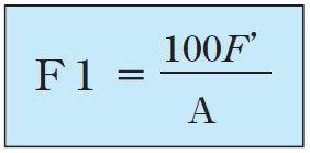
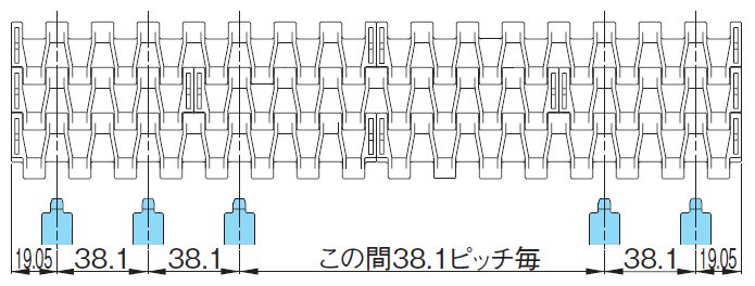
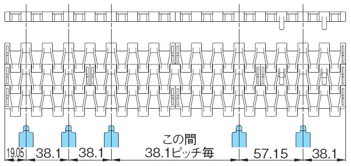
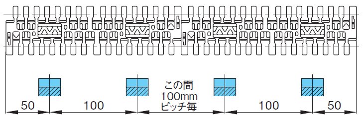
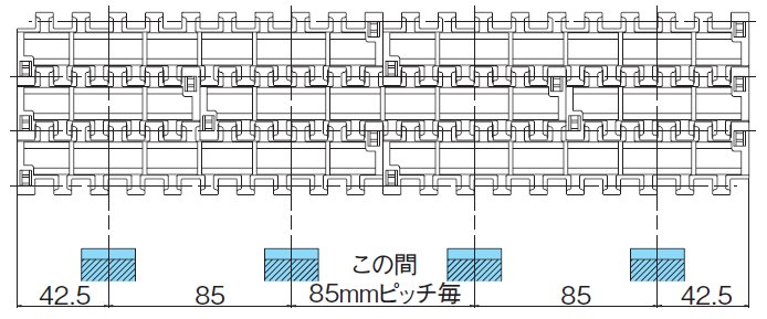
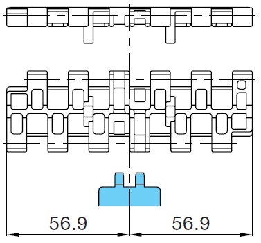
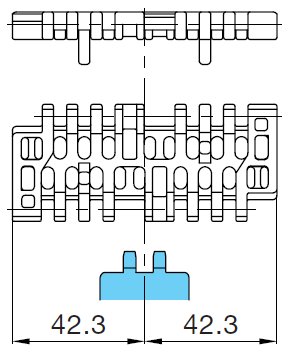
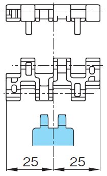
Please note that for wide Plastic modular chain, the number and installation position of sprockets will vary depending on the chain width and tension load rate. Also, to accommodate dimensional changes caused by expansion and contraction of the chain width due to temperature changes, the square and hexagonal holes of the sprockets are made larger than the shaft, allowing for lateral movement. Determining the sprocket mounting pitch The sprocket mounting pitch diagram for each chain is shown below. Check what percentage of the chain's allowable tension (MAX per 1m width) the tension F' converted into per 1m of chain width obtained using formula (2) is. Please note that this may change depending on the chain tension load factor F1. Calculation of tension load factor F1 (%)
F'... Chain width converted capacity kN/m {kgf/m} calculated using formula (2) A... Chain width 1m conversion capacity kN {kgf} at each operating temperature Please refer to the chain Allowable load graph. Wide Type
Mold-to-width type
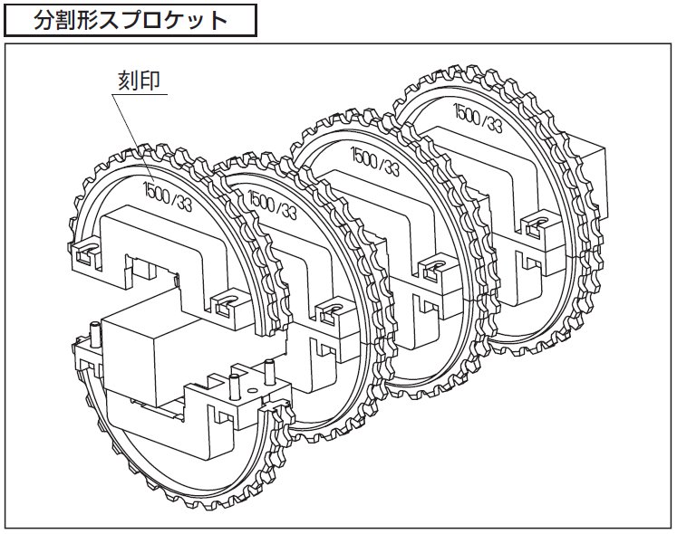
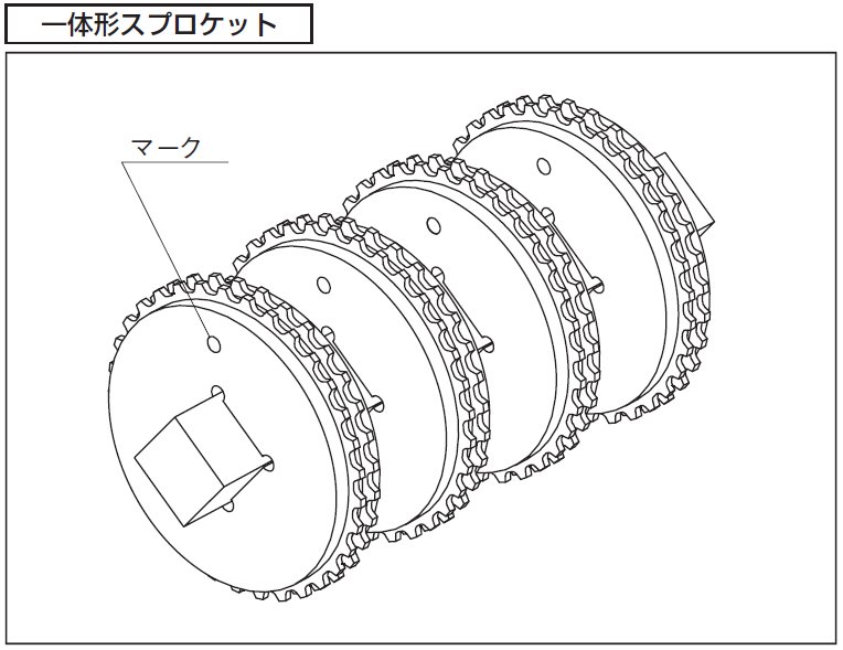
Handling sprocketsFor drive and driven shafts used with Plastic modular chain, square shafts are generally recommended, with the exception of special cases (mold-to-width types, perpendicular to TOD, etc.). Chains expand and contract with temperature changes, so sprockets should be installed so they can move freely laterally in the width direction. However, to prevent the chain from meandering, one (or two) sprockets should be secured in the center of both the drive and driven shafts with a set screw, set collar, or hex socket bolt. When installing sprockets on square shafts, use stamping and marks as a guide to ensure consistent orientation and tooth positioning. ■ Sprocket phase alignment Please install it on the shaft by aligning stamping and marks.
■ Chain expansion and contraction Plastic modular chain are made of resin, so they expand and contract with temperature changes. The linear expansion coefficient of the chain is approximately 15 x10 -5 (/℃) at 20℃. The amount of expansion of the nominal width (⊿W) can be calculated using the formula below. ⊿W = Chain nominal width x (ambient temperature - 20) x 15 x 10-5
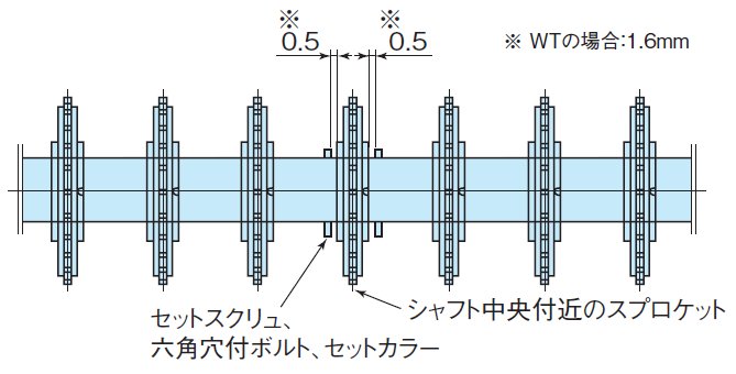
(Example) When using a K60 (1524mm) chain in an environment where the temperature rises from 20°C to 60°C ⊿W=1524×(60-20)×15×10-5=9.1mm ■ Fixing the sprocket The sprockets are loosely fitted to the shaft to absorb differences in thermal expansion between the chain and conveyor, and installation errors between the chain and sprocket. However, to prevent the chain from meandering, a gap of approximately 0.5 mm (1.6 mm for WT) is left on both sides of one sprocket near the center, and set screws, hex socket bolts, and set collars are attached.
*When using a chain with anti-snake tabs, be sure to secure the sprockets installed between the anti-snake attachments. ■ Chain installation Match the sprocket pitch to the specified mounting pitch (see the selection section) and wind the chain around it. *If the sprocket mounting pitch is not correct, the chain may ride up onto the sprocket and be damaged. Please check carefully. Back to Questions |
|||||||||||||||||||||||||||||||||||||||||||||||||||||||||||||||||||||||||||||||||||||||||||||||||||||||||||||||||||||||||||||||||||||||||||||||||||||||||||||||||||||||||||||||||||||||||||||||||||||||||||||||||||||||||||||||||||||||||||||||||||||||||||||||||||||||||||||||||||||||||||||||||||||||||||||||||||||||||||||||||||||||||||||||||||||||||||||||||||||||||||||||||||||||||||||||||||||||||||||||||||||||||||||||||||||||||||||||||||||||||||||||||||||||||||||||||||||||||||||||||||||||||||||||||||||||||||||||||||||||||||||||||||||||||||||||||||||||||||||||||||||||||||||||||||||||||||||||||||||||||||||||||||||||||||||||||||||||||||||||||||||||||||||||||||||||||||||||||||||||||||||||||||||||||||||||||||||||||||||||||||||||||||||||||||||||||||||||||||
| Q21 | What is the conveyor design for Plastic modular chain? | |||||||||||||||||||||||||||||||||||||||||||||||||||||||||||||||||||||||||||||||||||||||||||||||||||||||||||||||||||||||||||||||||||||||||||||||||||||||||||||||||||||||||||||||||||||||||||||||||||||||||||||||||||||||||||||||||||||||||||||||||||||||||||||||||||||||||||||||||||||||||||||||||||||||||||||||||||||||||||||||||||||||||||||||||||||||||||||||||||||||||||||||||||||||||||||||||||||||||||||||||||||||||||||||||||||||||||||||||||||||||||||||||||||||||||||||||||||||||||||||||||||||||||||||||||||||||||||||||||||||||||||||||||||||||||||||||||||||||||||||||||||||||||||||||||||||||||||||||||||||||||||||||||||||||||||||||||||||||||||||||||||||||||||||||||||||||||||||||||||||||||||||||||||||||||||||||||||||||||||||||||||||||||||||||||||||||||||||||||
| A21 |
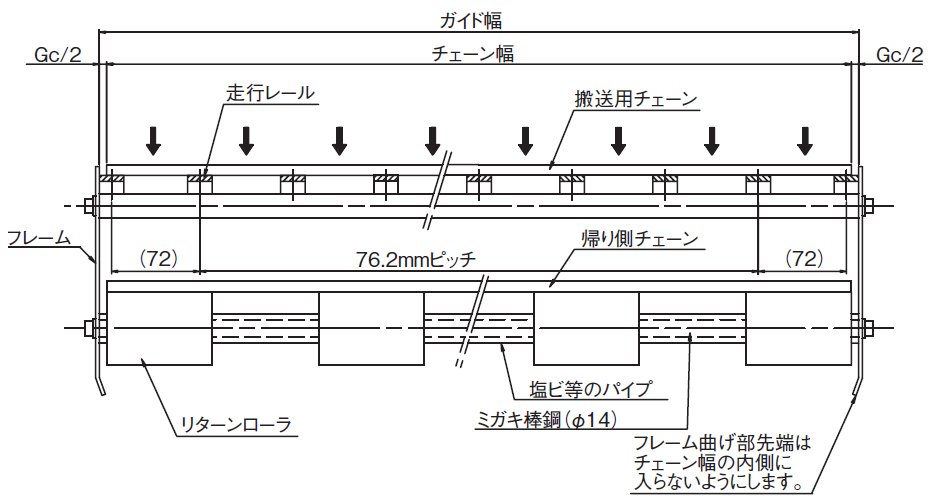
With Plastic modular chain, the chain should generally be supported by a rail on the transport side, and some slack should be provided on the return side. Slack below the drive sprocket is particularly important. A span of 500 to 1000 mm (depending on the chain type and tension load rate) and 50 to 100 mm of slack (during operation) should be maintained. If the slack is outside this range, the chain may skip teeth. Guide channel placementThe layout of guide channel will vary depending on the installation space, but an example is shown in the diagram below. *Please chamfer the rails and frame end faces of the drive sprocket to prevent interference.
Chain slack Refer to Table 1 below for the distance L between the return rollers that receive return-way chain under the drive sprocket, and leave 50 to 100 mm of slack in the chain between the return rollers. This slack prevents tooth skipping. Tooth skipping may occur if the slack is outside this range.
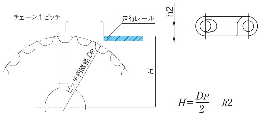
Note) 1. For mold-to-width types, please refer to the catalog technical notes when designing. 2. Please contact us regarding special conveyors such as pasteurizers. 3. Please refer to the catalog technical notes for installation of the nose bars on both ends. Meshing angle The meshing angle between the drive sprocket and chain must be 180° or more. If the angle is too small, teeth may skip. Rail End The distance C between the sprocket and the rail end should be one basic chain pitch. The driven side rail end should be bent or chamfered to prevent the chain from getting caught on the rail. Position of sprocket and rail Please refer to the diagram below.
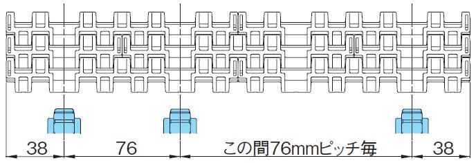
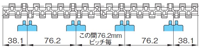
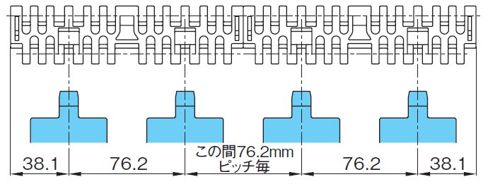
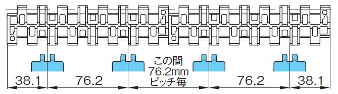
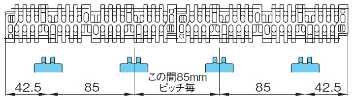
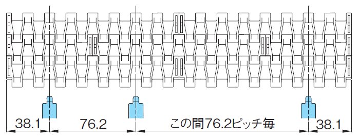
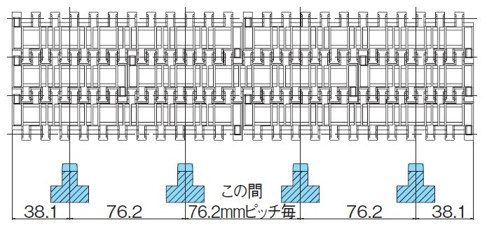
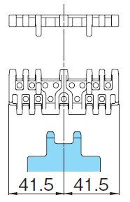
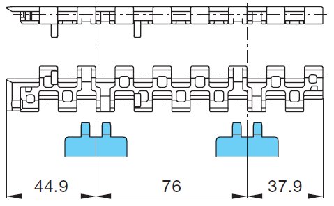
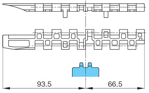
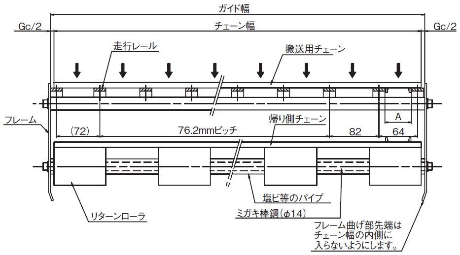
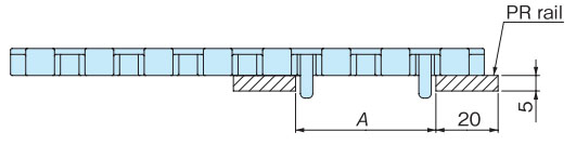
Rail installation example (at room temperature)Wide type (without anti-snake tab) Place the rails and sprockets alternately at equal intervals. Rail interval A is 76mm for BTN, 76.2mm for BT6, BT8, WT1500, WT3005, BTC8S, 76.2mm (rail width 25mm) for WT2500, 85mm for WT3086, WT2250, and 100mm (rail width 30mm) for WT3816.
Wide type (with anti-snake tab) (Chains with anti-snake tabs: BTN5-A, WT1505GK, WT1505GTOK, WT3005GK, WT3086GK) Install the anti-snake tab so that it does not interfere with the rail.
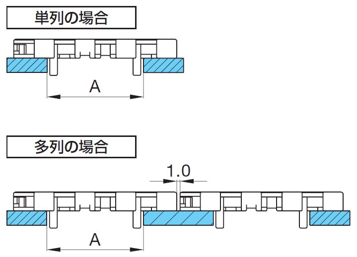
mold-to-width type (with anti-snake tab) For guide clearance of guided chains, refer to the table below. When using multiple strand, leave a gap of about 1 mm between the chains.
|
|||||||||||||||||||||||||||||||||||||||||||||||||||||||||||||||||||||||||||||||||||||||||||||||||||||||||||||||||||||||||||||||||||||||||||||||||||||||||||||||||||||||||||||||||||||||||||||||||||||||||||||||||||||||||||||||||||||||||||||||||||||||||||||||||||||||||||||||||||||||||||||||||||||||||||||||||||||||||||||||||||||||||||||||||||||||||||||||||||||||||||||||||||||||||||||||||||||||||||||||||||||||||||||||||||||||||||||||||||||||||||||||||||||||||||||||||||||||||||||||||||||||||||||||||||||||||||||||||||||||||||||||||||||||||||||||||||||||||||||||||||||||||||||||||||||||||||||||||||||||||||||||||||||||||||||||||||||||||||||||||||||||||||||||||||||||||||||||||||||||||||||||||||||||||||||||||||||||||||||||||||||||||||||||||||||||||||||||||||
| Q22 | Layout of the return side of Plastic modular chain | |||||||||||||||||||||||||||||||||||||||||||||||||||||||||||||||||||||||||||||||||||||||||||||||||||||||||||||||||||||||||||||||||||||||||||||||||||||||||||||||||||||||||||||||||||||||||||||||||||||||||||||||||||||||||||||||||||||||||||||||||||||||||||||||||||||||||||||||||||||||||||||||||||||||||||||||||||||||||||||||||||||||||||||||||||||||||||||||||||||||||||||||||||||||||||||||||||||||||||||||||||||||||||||||||||||||||||||||||||||||||||||||||||||||||||||||||||||||||||||||||||||||||||||||||||||||||||||||||||||||||||||||||||||||||||||||||||||||||||||||||||||||||||||||||||||||||||||||||||||||||||||||||||||||||||||||||||||||||||||||||||||||||||||||||||||||||||||||||||||||||||||||||||||||||||||||||||||||||||||||||||||||||||||||||||||||||||||||||||
| A22 |
The most common layout is the return roller support system, which is recommended because it allows for appropriate chain slack and can absorb chain elongation. If the chain has flights, it is necessary to ensure that the flights do not interfere with the rollers. Conveyor LayoutThere are various methods for receiving on the return side, such as "receiving on a return roller" or "receiving on a rail." Examples are shown below. *Notes 1. Please be especially careful when transferring via TOD etc. at end. 2. The entrance of the return rail should have a large radius of R40 or more. 3. Chains expand and contract due to temperature changes, so cut the chain so that there is an appropriate amount of slack in the catenary section and adjust it using a tensioner or similar. Return roller receiving method Conveyor side
Conveyor Plane
Adjust the roller installation interval (conveyor width direction) to match the width of the chain being used. Rail support system Conveyor side
Return side of flight chainOn the return side of a chain with flights or rubber, install it as shown in the diagram below so that the flights do not interfere with rollers, etc.
*For wide chains, install rollers at 765mm intervals. Back to Questions |
|||||||||||||||||||||||||||||||||||||||||||||||||||||||||||||||||||||||||||||||||||||||||||||||||||||||||||||||||||||||||||||||||||||||||||||||||||||||||||||||||||||||||||||||||||||||||||||||||||||||||||||||||||||||||||||||||||||||||||||||||||||||||||||||||||||||||||||||||||||||||||||||||||||||||||||||||||||||||||||||||||||||||||||||||||||||||||||||||||||||||||||||||||||||||||||||||||||||||||||||||||||||||||||||||||||||||||||||||||||||||||||||||||||||||||||||||||||||||||||||||||||||||||||||||||||||||||||||||||||||||||||||||||||||||||||||||||||||||||||||||||||||||||||||||||||||||||||||||||||||||||||||||||||||||||||||||||||||||||||||||||||||||||||||||||||||||||||||||||||||||||||||||||||||||||||||||||||||||||||||||||||||||||||||||||||||||||||||||||
| Q23 | Is forward and reverse operation possible with Plastic modular chain? | |||||||||||||||||||||||||||||||||||||||||||||||||||||||||||||||||||||||||||||||||||||||||||||||||||||||||||||||||||||||||||||||||||||||||||||||||||||||||||||||||||||||||||||||||||||||||||||||||||||||||||||||||||||||||||||||||||||||||||||||||||||||||||||||||||||||||||||||||||||||||||||||||||||||||||||||||||||||||||||||||||||||||||||||||||||||||||||||||||||||||||||||||||||||||||||||||||||||||||||||||||||||||||||||||||||||||||||||||||||||||||||||||||||||||||||||||||||||||||||||||||||||||||||||||||||||||||||||||||||||||||||||||||||||||||||||||||||||||||||||||||||||||||||||||||||||||||||||||||||||||||||||||||||||||||||||||||||||||||||||||||||||||||||||||||||||||||||||||||||||||||||||||||||||||||||||||||||||||||||||||||||||||||||||||||||||||||||||||||
| A23 |
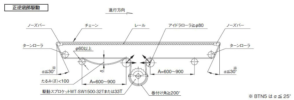
Forward and reverse operation is possible with Plastic modular chain. Please refer to the example below for forward and reverse operation.
In forward/reverse bottom drive, the idler roller is subjected to a load approximately 1.5 times the operating tension, so for wide conveyors (over 1m), select a shaft with sufficient rigidity or make sure the shaft is supported at three or more points. Back to Questions |
|||||||||||||||||||||||||||||||||||||||||||||||||||||||||||||||||||||||||||||||||||||||||||||||||||||||||||||||||||||||||||||||||||||||||||||||||||||||||||||||||||||||||||||||||||||||||||||||||||||||||||||||||||||||||||||||||||||||||||||||||||||||||||||||||||||||||||||||||||||||||||||||||||||||||||||||||||||||||||||||||||||||||||||||||||||||||||||||||||||||||||||||||||||||||||||||||||||||||||||||||||||||||||||||||||||||||||||||||||||||||||||||||||||||||||||||||||||||||||||||||||||||||||||||||||||||||||||||||||||||||||||||||||||||||||||||||||||||||||||||||||||||||||||||||||||||||||||||||||||||||||||||||||||||||||||||||||||||||||||||||||||||||||||||||||||||||||||||||||||||||||||||||||||||||||||||||||||||||||||||||||||||||||||||||||||||||||||||||||
| Q24 | I would like to manufacture a conveyor with a small transfer section. | |||||||||||||||||||||||||||||||||||||||||||||||||||||||||||||||||||||||||||||||||||||||||||||||||||||||||||||||||||||||||||||||||||||||||||||||||||||||||||||||||||||||||||||||||||||||||||||||||||||||||||||||||||||||||||||||||||||||||||||||||||||||||||||||||||||||||||||||||||||||||||||||||||||||||||||||||||||||||||||||||||||||||||||||||||||||||||||||||||||||||||||||||||||||||||||||||||||||||||||||||||||||||||||||||||||||||||||||||||||||||||||||||||||||||||||||||||||||||||||||||||||||||||||||||||||||||||||||||||||||||||||||||||||||||||||||||||||||||||||||||||||||||||||||||||||||||||||||||||||||||||||||||||||||||||||||||||||||||||||||||||||||||||||||||||||||||||||||||||||||||||||||||||||||||||||||||||||||||||||||||||||||||||||||||||||||||||||||||||
| A24 |
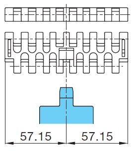
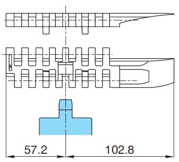
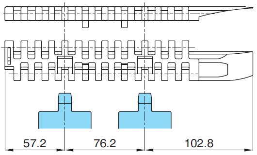
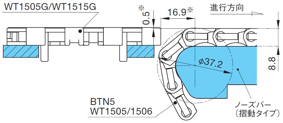
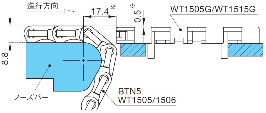
If you want to make the transfer area smaller, you can do so by using a nose bar. Also, please note that the transfer area can be made smaller with the BTC4-M. Nose bar in-line layoutThe layout of guide channel will vary depending on the installation space, but an example is shown in the diagram below.
*The dimensions in the diagram above are for reference only. Please make fine adjustments depending on the transfer status of the transported items. *Depending on the shape of the transported item (unstable), even a slight jerk of the chain may cause a malfunction.
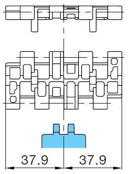
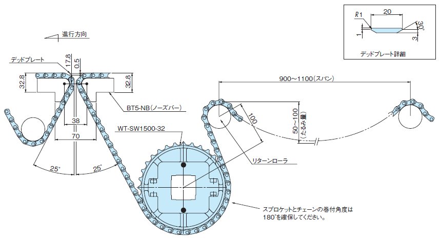
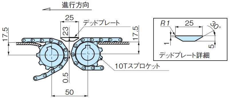
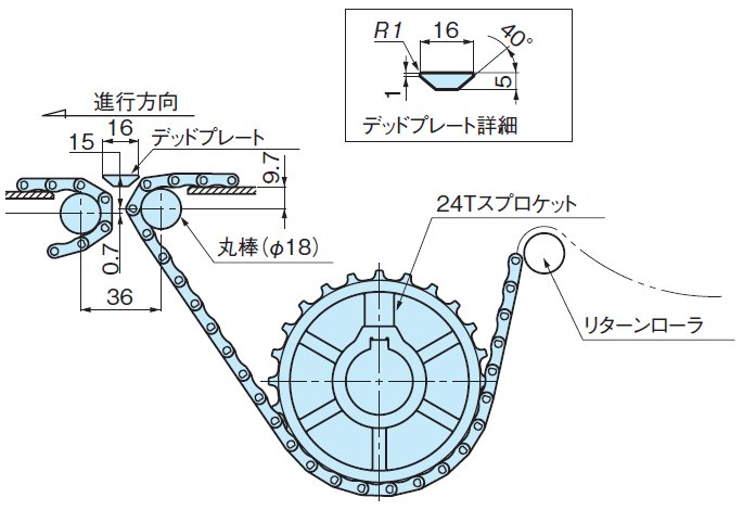
By using the WT1500 series or BTN5, it is possible to in-line conveyors in a straight butt joint. The dead plate used at in-line can be narrowed to 20 mm. Note) 1. *The part marked with an asterisk (*) may require adjustment depending on the type of item being transported. 2. Only the WT1500 series and BTN5 chains are compatible. The WT1505G type is not compatible. BTC4-M type in-line layoutIn the case of a straight line transfer with a 10T sprocket
In the case of a straight line transfer with a φ18 shaft
Note) Adjust the dead plate level slightly depending on the transfer status of the transported items. Back to Questions |
|||||||||||||||||||||||||||||||||||||||||||||||||||||||||||||||||||||||||||||||||||||||||||||||||||||||||||||||||||||||||||||||||||||||||||||||||||||||||||||||||||||||||||||||||||||||||||||||||||||||||||||||||||||||||||||||||||||||||||||||||||||||||||||||||||||||||||||||||||||||||||||||||||||||||||||||||||||||||||||||||||||||||||||||||||||||||||||||||||||||||||||||||||||||||||||||||||||||||||||||||||||||||||||||||||||||||||||||||||||||||||||||||||||||||||||||||||||||||||||||||||||||||||||||||||||||||||||||||||||||||||||||||||||||||||||||||||||||||||||||||||||||||||||||||||||||||||||||||||||||||||||||||||||||||||||||||||||||||||||||||||||||||||||||||||||||||||||||||||||||||||||||||||||||||||||||||||||||||||||||||||||||||||||||||||||||||||||||||||
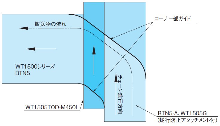
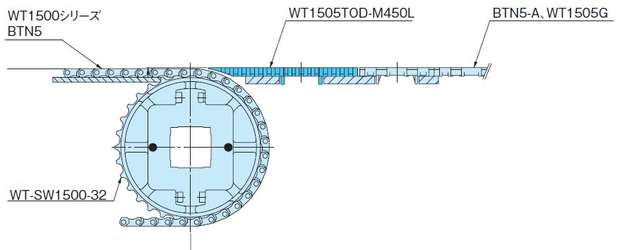
| Q25 | I want to eliminate residual transported items on a cross conveyor. | |||||||||||||||||||||||||||||||||||||||||||||||||||||||||||||||||||||||||||||||||||||||||||||||||||||||||||||||||||||||||||||||||||||||||||||||||||||||||||||||||||||||||||||||||||||||||||||||||||||||||||||||||||||||||||||||||||||||||||||||||||||||||||||||||||||||||||||||||||||||||||||||||||||||||||||||||||||||||||||||||||||||||||||||||||||||||||||||||||||||||||||||||||||||||||||||||||||||||||||||||||||||||||||||||||||||||||||||||||||||||||||||||||||||||||||||||||||||||||||||||||||||||||||||||||||||||||||||||||||||||||||||||||||||||||||||||||||||||||||||||||||||||||||||||||||||||||||||||||||||||||||||||||||||||||||||||||||||||||||||||||||||||||||||||||||||||||||||||||||||||||||||||||||||||||||||||||||||||||||||||||||||||||||||||||||||||||||||||||
| A25 |
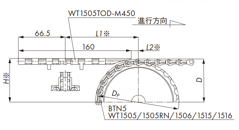
We recommend using a chain with the transfer section integrated into one unit (TOD type, GTO type). Please refer to the layout etc. below. Orthogonal transport layoutBy combining with WT1505TOD/GTO or WT2505TOD, dead plates become unnecessary and orthogonal transport of transported items becomes possible.
The installation dimensions for each chain are shown below. Insertion transport (WT1505TOD/WT1500)
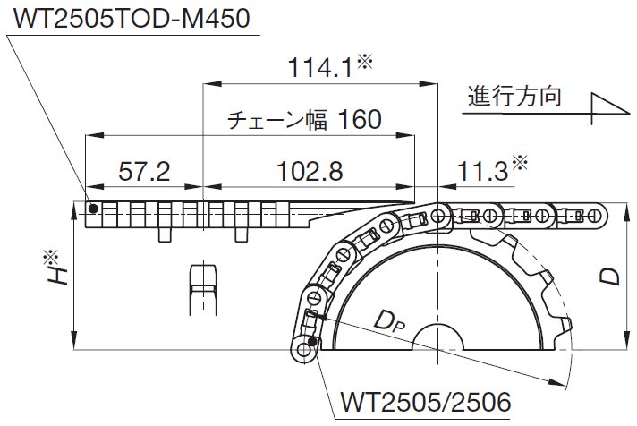
Note) * indicates adjustment is required depending on the transported items. Insertion transport (WT2505TOD/WT2500)
■WT2505TOD-M450
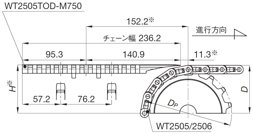
Note) * indicates adjustment is required depending on the transported items. ■WT2505TOD-M750
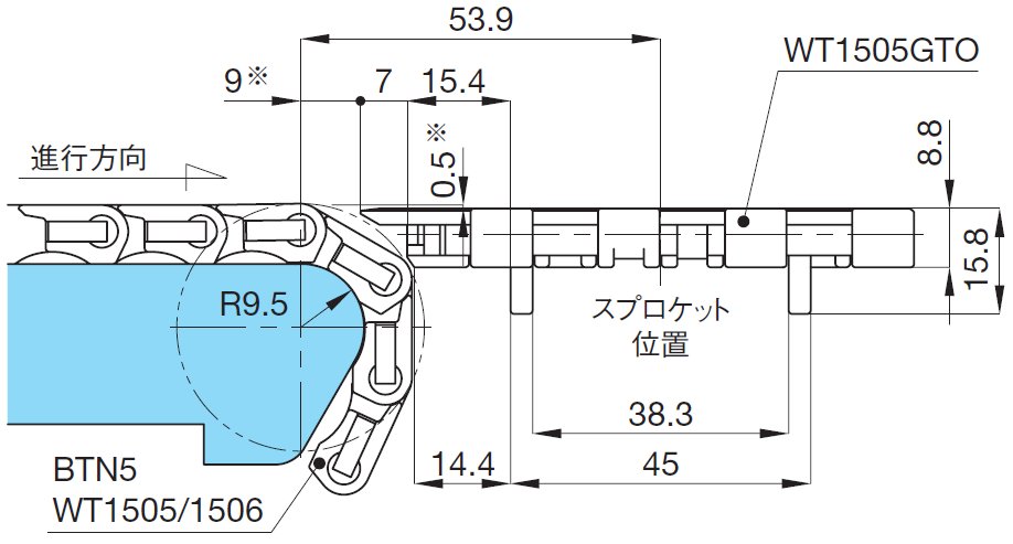
Note) * indicates adjustment is required depending on the transported items. Discharge conveyance (WT1505GTO/WT1500)
Note) * indicates adjustment is required depending on the transported items. By using our nose bars and GTO/TOD type chains, smooth 90° angle changes in conveyance are possible without the use of dead plates that are normally required. Orthogonal transport between WT1500 and WT1505GInsertion transport (WT1500/WT1505G/WT1515G)
Note) * indicates adjustment is required depending on the transported items. Discharge conveyance (WT1500/WT1505G/WT1515G)
Note) * indicates adjustment is required depending on the transported items. Back to Questions |
|||||||||||||||||||||||||||||||||||||||||||||||||||||||||||||||||||||||||||||||||||||||||||||||||||||||||||||||||||||||||||||||||||||||||||||||||||||||||||||||||||||||||||||||||||||||||||||||||||||||||||||||||||||||||||||||||||||||||||||||||||||||||||||||||||||||||||||||||||||||||||||||||||||||||||||||||||||||||||||||||||||||||||||||||||||||||||||||||||||||||||||||||||||||||||||||||||||||||||||||||||||||||||||||||||||||||||||||||||||||||||||||||||||||||||||||||||||||||||||||||||||||||||||||||||||||||||||||||||||||||||||||||||||||||||||||||||||||||||||||||||||||||||||||||||||||||||||||||||||||||||||||||||||||||||||||||||||||||||||||||||||||||||||||||||||||||||||||||||||||||||||||||||||||||||||||||||||||||||||||||||||||||||||||||||||||||||||||||||
| Q26 | [Plastic modular chain] What sprockets can be used with chains that have float-preventive tabs? | |||||||||||||||||||||||||||||||||||||||||||||||||||||||||||||||||||||||||||||||||||||||||||||||||||||||||||||||||||||||||||||||||||||||||||||||||||||||||||||||||||||||||||||||||||||||||||||||||||||||||||||||||||||||||||||||||||||||||||||||||||||||||||||||||||||||||||||||||||||||||||||||||||||||||||||||||||||||||||||||||||||||||||||||||||||||||||||||||||||||||||||||||||||||||||||||||||||||||||||||||||||||||||||||||||||||||||||||||||||||||||||||||||||||||||||||||||||||||||||||||||||||||||||||||||||||||||||||||||||||||||||||||||||||||||||||||||||||||||||||||||||||||||||||||||||||||||||||||||||||||||||||||||||||||||||||||||||||||||||||||||||||||||||||||||||||||||||||||||||||||||||||||||||||||||||||||||||||||||||||||||||||||||||||||||||||||||||||||||
| A26 |
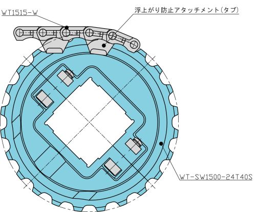
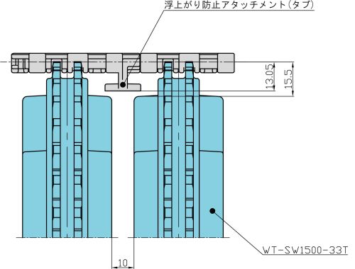
■WT1515T-FW and WT1516T-FW chains with float-preventive tabs
*It can be used because there is no interference between float-preventive tabs and the shaft. ■Conceptual image
■Molded sprocket
■Processed sprockets
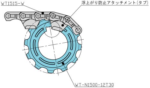
*Please refer to the diagram and explanation below for the reason. ■WT-N1500-12T float-preventive tabs and key part
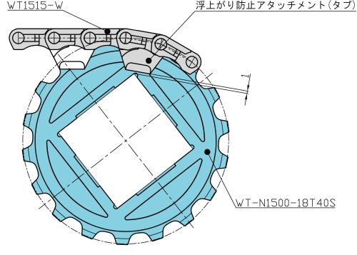
■WT-N1500-18T There is no interference between float-preventive tabs and the square shaft,
|
|||||||||||||||||||||||||||||||||||||||||||||||||||||||||||||||||||||||||||||||||||||||||||||||||||||||||||||||||||||||||||||||||||||||||||||||||||||||||||||||||||||||||||||||||||||||||||||||||||||||||||||||||||||||||||||||||||||||||||||||||||||||||||||||||||||||||||||||||||||||||||||||||||||||||||||||||||||||||||||||||||||||||||||||||||||||||||||||||||||||||||||||||||||||||||||||||||||||||||||||||||||||||||||||||||||||||||||||||||||||||||||||||||||||||||||||||||||||||||||||||||||||||||||||||||||||||||||||||||||||||||||||||||||||||||||||||||||||||||||||||||||||||||||||||||||||||||||||||||||||||||||||||||||||||||||||||||||||||||||||||||||||||||||||||||||||||||||||||||||||||||||||||||||||||||||||||||||||||||||||||||||||||||||||||||||||||||||||||||