technical data Clutch Selection
If you would like to see the selection procedures and important points, please proceed below.
If you would like to narrow down or tentatively select a product series,
Please click here.
Selection method
Please clarify the application of the Cam Clutch (overrunning, indexing, backstop). Selection methods differ depending on the application, so please select a Cam Clutch according to the appropriate procedure. If you have any of the following model numbers, please contact us.
- (1) Cam clutch box
- (2) Clutch used for stopper feeding (indexing)
1. In case of overrunning
- (1) Calculate the torque applied to the cam clutch using the formula below.
Torque Calculation Formula
SI unit T = 60000 × kW 2 π × N × Sf(N・m)
{weight unit} T = 974 × kW N × Sf{kgf・m}
T Torque applied to the cam clutch (N・m) kW Cam clutch shaft transmission power (kW) N Cam clutch shaft rotation speed (r/min) S.f Service factor (see table below) Service factor table
conditions S.f No impact torque 1~1.5 There is some impact torque 1.5~2.5 Impact torque 2~3 Strong impact torque 4~6 - (2) Maximum idling rotation speed
- (3) Shaft hole diameter
- (4) Installation method
- (5) Other (atmospheric conditions, maintenance, etc.)
Select a model number that satisfies the above conditions from among the overrunning clutches (see the list of series compatible with each application above and each page).
| Series | |||||||||||||||||||
|---|---|---|---|---|---|---|---|---|---|---|---|---|---|---|---|---|---|---|---|
| Purpose | MZ MZ-G |
BB | PB | 200 | LD | ML | MG | MI | MX | MI-S | BS | BR BR(P) |
MG-R | MA | MR | Cam clutch box |
MZ-C | MG-C | |
| Dual drive ・ Two-speed drive |
High speed idling and high speed engagement | ○ | ◎ | ○ | |||||||||||||||
| High speed freewheeling and medium to low speed engagement | ◎ | ◎ | ◎ | ||||||||||||||||
| High speed idling/low speed engagement | ◎ | ◎ | ◎ | ◎ | |||||||||||||||
| Low-medium speed freewheeling/low-medium speed engagement | ◎ | ○ | ○ | ○ | ○ | ○ | ○ | ◎ | ○ | ||||||||||
| Forward rotation engagement, reverse rotation idle | ◎ | ○ | ○ | ○ | ○ | ○ | ○ | ○ | ◎ | ○ | |||||||||
| Freewheeling | ◎ | ○ | ○ | ○ | ○ | ○ | ○ | ◎ | ◎ | ○ | |||||||||
| Manual type | ○ | ○ | ○ | ◎ | ◎ | ○ | |||||||||||||
If Service factor (Sf) is unknown, calculate it using the following procedure.
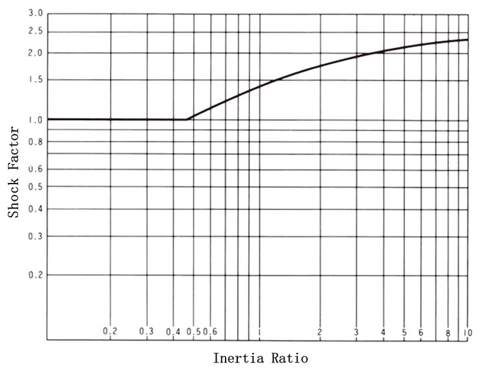
Sf = % starting torque of prime mover rating × shock factor (max 2.5)
The impact coefficient is
Inertia ratio =
total moment of inertia on the load side
(Clutch shaft equivalent)
Input side total moment of inertia
(Clutch shaft equivalent)
Please find it from the diagram below.
Impact Factor
2. Indexing
2.1 Indexing feed cam clutch
- (1) Calculate the torque applied to the cam clutch using formula A or formula B.
Note: The above formula cannot be applied to indexing that does not use a crank mechanism. A type
T = I・θ・N2 101750 + TB
T Torque applied to the cam clutch N・m I Total moment of inertia on the load side (converted to cam clutch shaft) kg・m 2 θ Feed angle per cycle (degrees) (Cam clutch shaft conversion) N Indexing frequency per minute (times/min) TB Load side brake torque N・m (Cam clutch shaft conversion) B type
T = 60000 × P 2π × n ・ ℓ2 ℓ1 × 2.5
T Torque applied to the cam clutch N・m P Transmission power kW n Crankshaft rotation speed r/min ℓ1 crank length m ℓ2 Swing arm length m 2.5 coefficient - (2) Highest indexing frequency
- (3) Feed angle (θ) 90° or less for all series except MI-S
- (4) N × θ ≦ 20000 (for high, medium, and low speeds and small feed angles)
N × θ ≦ 50000 (low speed/large feed angle) - (5) Expected accuracy
If you are looking for particularly high precision feeding, please use the MX series.
Also, please use high-precision anti-reverse clutches and brakes. - (6) Shaft hole diameter
- (7) Installation method
- (8) Other (lifespan, maintenance, etc.)
Select a model number that meets the above conditions from among the indexing cam clutches (see the list of compatible series by application below and each page).
| Series | ||||||||||||||||||
|---|---|---|---|---|---|---|---|---|---|---|---|---|---|---|---|---|---|---|
| Purpose | MZ MZ-G |
BB | PB | 200 | LD | ML | MG | MI | MX | MI-S | BS | BR BR(P) |
MG-R | MA | MR | Cam clutch box |
MZ-C | MG-C |
| High speed/small feed angle | ◎ | |||||||||||||||||
| Medium to low speed, small feed angle | ○ | ○ | ○ | ○ | ○ | ○ | ◎ | ○ | ○ | |||||||||
| Low speed/large feed angle | ◎ | |||||||||||||||||
| Prevents reverse intermittent feed | ○ | ○ | ○ | ○ | ○ | ○ | ◎ | ◎ | ○ | |||||||||
| Feed with stopper | Please contact us for details. | |||||||||||||||||
| For gear changes | ○ | ○ | ○ | ○ | ○ | ○ | ○ | ◎ | ||||||||||
2.2 Backstop for intermittent feed
Use the same model number as the feed cam clutch, or a model number one rank smaller.
Furthermore, when using the MX series, please make sure that it falls within the range below each curve in the graph below.
MX Series Usage Range
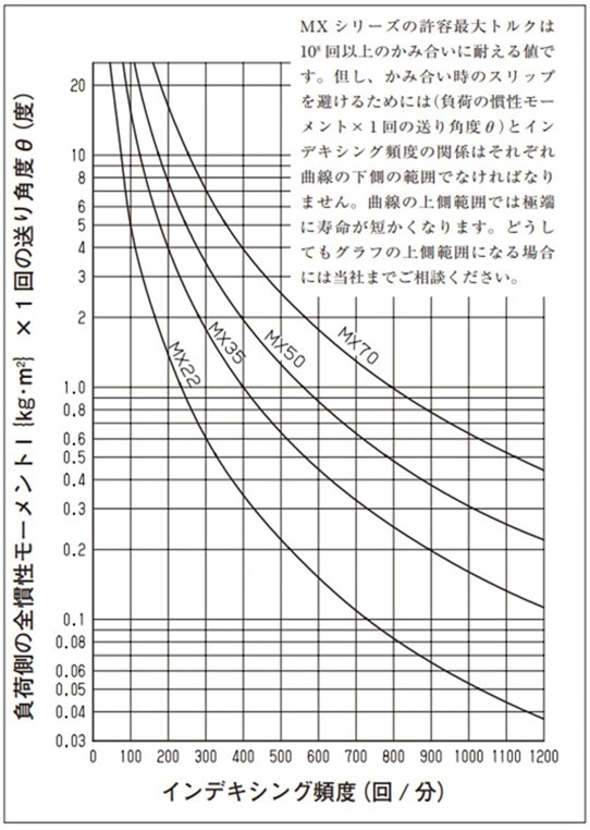
[Click to enlarge]
3. Selection method in case of backstop
3.1 Calculation of torque applied to the cam clutch
(1) Preventing reverse rotation of belt conveyors
[Step 1] Calculate the no-load power (P1). P1 = 0.06 × f × W × V × ℓ + ℓ0 367 (kW)
[Step 2] Calculate the horizontal load power (P2). P2 = f × Qt × ℓ + ℓ0 367 (kW)
[Step 3] Calculate the vertical load power (P3). P3 = h × Qt 367 (kW)
[Step 4] Calculate the reverse power (Pr). Pr = P 3- 0.7(P 1 + P 2)(kW)
[Step 5] Calculate the reverse torque (T). SI units: T = 60000 × Pr 2 π × N × Sf (N・m) {weight unit} T = 974 × Pr N × Sf {kgf・m}
- f = coefficient of rolling friction of the roller
= 0.03 (normal value) - W = Mass of moving parts other than the transported object {kg/m}
(Use the values in the table below depending on the belt width)Belt width mm 400 450 500 600 750 900 1050 1200 1400 1600 1800 2000 Mass W 22.4 28 30 35.5 53 63 80 90 112 125 150 160 - V = conveyor speed m/min
- Qt = maximum conveyance t/h
- h = lifting height m
- ℓ = horizontal center distance between head and tail belt wheels m
- ℓ 0 = center distance correction factor m
= 49m (normal value) - N = Rotational speed of the BS Cam Clutch mounting shaft r/min
- Sf = Service factor
(Use the values in the table below depending on the frequency of load application)Less than a few times a day 1.5 Several times a day or more 2.0
(2) Bucket elevator reverse prevention
[Step 1] Calculate the reverse torque (T). SI units: T =
(L + D) × Qt × D × 9800
120 × V
× Sf(N・m)
{Weight unit} T =
(L + D) × Qt × D × 1000
120 × V
× Sf{kg・m}
[Step 2] Select a size where the reverse torque (T) is within the maximum allowable torque.
- Note) 1. When calculating the reverse torque, we recommend using the maximum transport amount (Qt) that is the largest possible value based on the conveyor's capacity. Unexpected reversals of conveyors often occur when the conveyor is loaded to its full capacity.
- Note 2: For conveyors other than those listed above, calculate the reverse torque using the formula specific to each conveyor. In this case, too, calculate assuming that the conveyor is subjected to the maximum load capacity.
- L = lifting height m
- D = Pitch circle diameter of head conveyor chain wheel m
- Qt = maximum conveyance t/h
- V = conveyor speed m/min
- Sf = Service factor
(Use the values in the table below depending on the frequency of load application)Less than a few times a day 1.5 Several times a day or more 2.0
- T = Prime mover trip torque
- kW = Motor capacity (kW)
- N = Cam clutch idling speed r/min
- S = Motor stall torque %
- Tmax = Maximum allowable torque in the catalogue
(3) Selection by engine trip
If there is a possibility that the drive motor may trip and stop due to problems during transport or incorrect wiring, select using the following formula.
SI unit T = 60000 × kW 2 π × N × S 100 ≦ Tmax(N・m)
{Weight unit} T = 974 × kW N × S 100 ≦ Tmax{kgf・m}
Note: The above selection formula is for the BS series. For other series, please contact us.
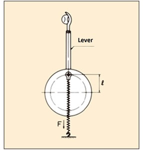
(4) Backstops subject to repeated impact loads (tennis machines, pitching machines, etc.)
Required torque calculation
T = F × ℓ × 3.0
- T: Torque applied to the cam clutch (N・m)
- F: Maximum spring tension (N)
- ℓ: Eccentricity (load)
- 3.0: Coefficient
3.2 Idling rotation speed
3.3 Shaft hole diameter
3.4 Installation method
Quick reference table of reverse torque and rotation speed
(MG-R r/min is for continuous idling)
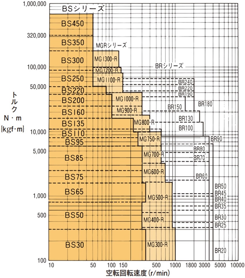
[Click to enlarge]
Select a model number from the backstop cam clutches (see the list of compatible series by application below and each page) that satisfies each of the above items.
| Series | ||||||||||||||||||
|---|---|---|---|---|---|---|---|---|---|---|---|---|---|---|---|---|---|---|
| Purpose | MZ MZ-G |
BB | PB | 200 | LD | ML | MG | MI | MX | MI-S | BS | BR BR(P) |
MG-R | MA | MR | Cam clutch box |
MZ-C | MG-C |
| Low speed idling | ○ | ○ | ○ | ○ | ○ | ○ | ○ | ◎ | ○ | |||||||||
| Medium speed idle | ○ | ○ | ○ | ○ | ○ | ○ | ◎ | |||||||||||
| High-speed idling | ○ | ◎ | ◎ | ○ | ||||||||||||||
| Backstop with repeated impact loads | ◎ | |||||||||||||||||

