| Q1 |
Is Belt Sprockets alignment necessary? |
| A1 |
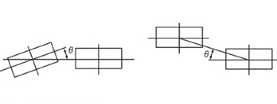
Even if Synchronous Belts Belt Sprockets is properly aligned, the timing belt does not run in the center of Belt Sprockets, but tends to lean to one side.
Although this force is very weak, if Belt Sprockets is not properly aligned, it may run close to the edge of Belt Sprockets and be pressed hard against the guide flange, potentially damaging or cutting it. Also, the guide flange may fall off.
Adjust Belt Sprockets alignment to within the tolerances in the table below.
| Belt size |
All varieties |
| Belt width mm |
30 or less |
30~50 |
50~100 |
Over 100 |
| Allowable parallelism |
5/1000 or less |
4/1000 or less |
3/1000 or less |
2/1000 or less |
| θ minutes |
17 or less |
13 or less |
10 or less |
6 or less |
[Click to enlarge]
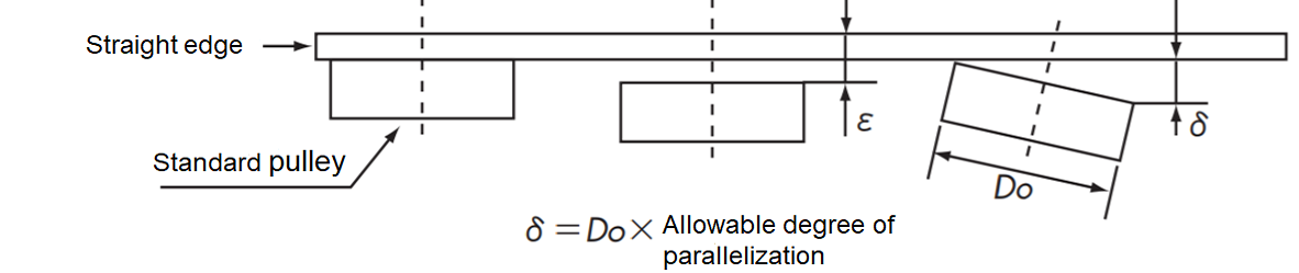
■ Pulley adjustment method
As shown in the figure, a straight edge is placed on the reference pulley, and the other pulleys are brought into contact with the entire surface of the straight edge (ε = 0), allowing the pulleys to be lined up in the correct position.
In addition, by keeping δ in the figure below the limit, it is possible to simultaneously achieve parallelism of the axis.
[Click to enlarge]
Back to Questions
|
| Q2 |
How do I install Lock Belt Sprockets? |
| A2 |
- Wipe off any dirt from the shaft surface and apply a thin layer of oil or grease (do not use any that contain molybdenum-based anti-friction agents).
- For S-type specifications... Remove the sleeve tightening bolt, wipe the pulley and sleeve contact surfaces clean, and apply oil or grease. Also apply it to the threaded portion and seat of the tightening bolt. (Products containing molybdenum-based anti-friction agents are not permitted.)
For S-type plated specifications... Remove the sleeve tightening bolt and wipe the pulley and sleeve contact surfaces clean. Applying oil or grease is not necessary, so do not use it.
- Lightly tighten the fastening bolts to temporarily assemble the sleeve.
- 3) Gently push Lock Belt Sprockets that you temporarily assembled in step 3 into the designated position by hand.
- Tighten the bolts evenly in diagonal order with 1/4 of the rated tightening torque MA.
- Increase the tightening torque to 1/2 of the MA and tighten in the same manner as in 5).
- Increase the tightening torque to the rated value and tighten in the same manner as steps 5) and 6).
Precautions when installing Lock Belt Sprockets
- Always use a torque wrench when tightening the clamping bolts. Observe the tightening instructions and tightening torque MA. Using a wrench other than a torque wrench or tightening by hand will result in inaccuracy and may lead to accidents such as slippage or deformation.
- Tightening a bolt with a torque greater than the specified torque may cause the bolt to break. Tightening a bolt with a torque less than the specified torque may cause the bolt to loosen, so be sure to tighten it to the specified torque MA.
- Do not use any tightening bolts other than those provided with this product. Doing so may result in damage to the bolts or other accidents. If you need new bolts due to loss or replacement, please contact us.
Back to Questions
|
| Q3 |
How to install the flange? |
| A3 |
■ Fixing flanges
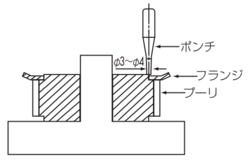
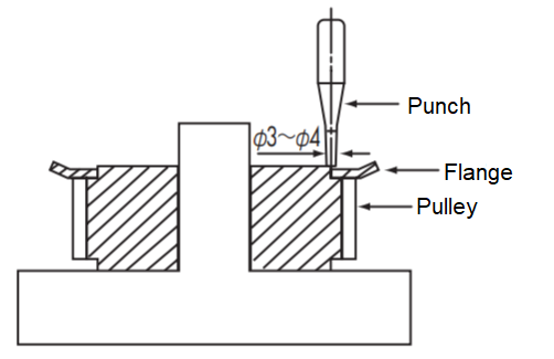
Crimping method
Press flanges and turned flanges are usually fixed by crimping with a punch as shown in the diagram below. The number of crimps used should follow the following standards.
| Tip diameter mm |
30 or less |
Over 30 and under 50 |
Over 50 and under 120 |
Over 120 and under 250 |
| Number of rivets |
4 |
8 |
12 |
16 |
Note
- Place the pulley on a flat surface and crimp the flange with a crimping punch.
- When crimping the side opposite the hub, insert the hub into a cylindrical jig placed on the board and crimp in a stable position.
 [Click to enlarge]
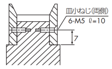
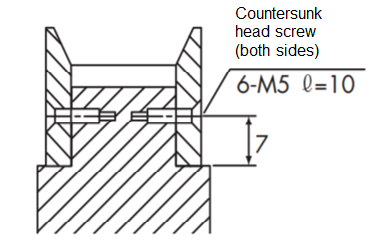
Screw fastening method
The turned flange of the P8M and P14M large tooth count pulleys may be fixed to the pulley body with flat head machine screws depending on how it is used. The number of flat head machine screws in the table below is the minimum number.
| Tip diameter mm |
120 or less |
Over 120 and under 250 |
Over 250 and under 450 |
Over 450 and under 650 |
| Number of screws |
4 |
6 |
8 |
12 |
 [Click to enlarge]
Knurling method
Another commonly used method is to knurl and crimp the part on a lathe.
Back to Questions
|
| Q4 |
How to select Belt Sprockets? (Selection based on power) |
| A4 |
- Use the simple selection table in the Tsubaki Synchronous Belts transmission catalog to provisionally select the belt size based on the design power and small pulley rotation speed.
- Please provisionally select the belt width and number of teeth on the pinion pulley from the standard transmission capacity table in the catalog. When doing so, please note the following:
- Select a pinion tooth number other than the colored part of the standard transmission capacity.
- Select a small pulley so that its pitch diameter is greater than the belt width.
- Make sure that the usable range of the pinion shaft hole satisfies the diameter of the shaft being used.
- Determine the number of teeth on the large pulley based on the number of teeth on the small pulley and the speed ratio. Also, check the shaft bore diameter to be used.
Back to Questions
|
| Q5 |
How to select Belt Sprockets? (Selection based on torque) |
| A5 |
- Use the simple selection table in the Tsubaki Synchronous Belts transmission catalog to provisionally select the belt size based on the design torque and small pulley rotation speed.
- Please provisionally select the belt width and number of teeth on the pinion pulley from the standard transmission torque table in the catalog. When doing so, please note the following:
- Select a pinion tooth number other than the colored portion of the standard transmission torque.
- Select a small pulley so that its pitch diameter is greater than the belt width.
- Make sure that the usable range of the pinion shaft hole satisfies the diameter of the shaft being used.
- Determine the number of teeth on the large pulley based on the number of teeth on the small pulley and the speed ratio. Also, check the shaft bore diameter to be used.
Back to Questions
|
| Q6 |
Why are six or more meshing teeth required? |
| A6 |
Unlike metal chains and gears, Synchronous Belts teeth are made of rubber covered with nylon fabric, so they are not suitable for transmission with just one tooth; multiple teeth are required to bear the load.
If the number of meshing teeth with Belt Sprockets is less than 6, the load per tooth will be large and may cause tooth chipping.If the number of meshing teeth is 5 or 4, please add the "meshing correction coefficient" listed in the catalog when selecting a pulley.
For drive pulleys, please consider using a minimum of six meshing teeth with a meshing angle of 120 degrees or greater.
Back to Questions
|
| Q7 |
What precautions should be taken when using small pulleys at high speeds? |
| A7 |
The combinations shown in the colored sections of kW ratings table in Synchronous Belts transmission catalogue should be avoided as they will cause the small pulley to rotate at high speeds, accelerating bending fatigue of the core wire inside Synchronous Belts and shortening its lifespan.
Back to Questions
|
| Q8 |
What should I be careful of when using a servo motor? |
| A8 |
If Synchronous Belts circumferential speed is high, the following may occur:
- If Belt Sprockets speed exceeds 33 m/s, runout and vibration may occur, so be sure to maintain balance.
- When selecting Synchronous Belts, we recommend that you consider the torque based on the servo motor's characteristics.
Back to Questions
|
| Q9 |
What material are Belt Sprockets made of? |
| A9 |
The following pulley materials are suitable:
Unit: g/cm3
| Material |
Material Symbol |
unit mass |
| Carbon steel for machine structures |
S45C |
7.85 |
| aluminum alloy |
A2017-T4 |
2.8 |
| stainless steel |
SUS304 |
7.8 |
Back to Questions
|
| Q10 |
What is the surface treatment for Belt Sprockets? |
| A10 |
Various surface treatments are possible depending on the application, so please consider them.
| Types of surface treatment |
effect |
Applicable material |
| Black Oxide |
Rust prevention and decoration |
carbon steel |
| electrogalvanizing |
Rust prevention and decoration |
carbon steel |
| Electroless nickel-phosphorus plating |
Rust prevention and decoration |
carbon steel |
| Anodized aluminum |
Rust prevention |
aluminum alloy |
| Hard anodized aluminum |
Rust prevention and wear resistance |
aluminum alloy |
Back to Questions
|
| Q11 |
What about backlash-less tooth profiles? |
| A11 |
Synchronous Belts normally have backlash when meshing, but for Synchronous Belts drives that require extremely accurate rotation, such as robots, electronic component assembly machines, NC devices, printers, and plotters, we manufacture pulleys with special backlash-free tooth profiles that reduce backlash and suppress rotation Angular Misalignment, so please contact us for details.
Back to Questions
|
| Q12 |
Can you manufacture custom-made products other than those listed in the catalog? |
| A12 |
Pulleys with dimensions, number of teeth, and materials other than those listed in the catalogue can also be manufactured, so please contact our customer service or a dealer.
Back to Questions
|
| Q13 |
What is the ambient temperature at which Belt Sprockets can be used? |
| A13 |
Use in a normal environment with a temperature range of -15°C to 80°C (aluminum: 0°C to 50°C).
Back to Questions
|
| Q14 |
Is it compatible with other companies' products? |
| A14 |
The pulleys for Tsubaki PX Belt have our own unique tooth shape and cannot be used with other companies' belts.
Please use in combination with Tsubaki Synchronous Belts.
Back to Questions
|
| Q15 |
What should I be careful of before use? |
| A15 |
Important points to note are listed in the "Belt Sprockets" catalog. Please be sure to read the "Instruction Manual" page before use.
Back to Questions
|
| Q16 |
What should I pay attention to when installing Synchronous Belts on Belt Sprockets? |
| A16 |
Synchronous Belts do not stretch even when force is applied.
When installing on Belt Sprockets, move the pulley shaft and idler shaft before installing.
Forcing Belt Sprockets over the guide flange may result in an accident, so please avoid doing so.
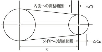
In two-shaft transmissions that do not use idlers, provide some adjustment space for the distance between the shafts.
■ Adjust the distance between the two shafts
Unit: mm
|
Belt length |
kinds |
P2M・P3M・P5M
UP3M・UP5M |
P8M・P14M
UP8M・UP14M |
| △Co |
Under 500 |
3 |
3 |
| 500~1000 |
5 |
5 |
| 1001~2000 |
10 |
10 |
| Over 2000 |
15 |
15 |
| △Ci |
common |
10 |
15 |
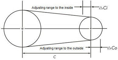 [Click to enlarge]
Back to Questions
|
| Q17 |
What should I be careful about when using Synchronous Belts and pulleys? |
| A17 |
Use in a clean atmosphere.
If Synchronous Belts and pulleys are to be used in a dusty environment where they may be exposed to large amounts of water, oil, or solvents, please cover them to protect them. In environments with high levels of moisture and oil in the air, the "Ultra PX Belt HA Specification (Oil-Resistant/Water-Resistant)" may be suitable, and in environments with high levels of moisture, the "PX Belt Water-Resistant" may be suitable, so please consider these options.
For pulleys, stainless steel specifications that are effective in corrosion resistance and chemical resistance, or surface treatment specifications that are effective in rust prevention may be available, so please consider these.
Back to Questions
|
| Q18 |
What type of noise? |
| A18 |
Generally, it is as follows:
- ①The impact noise that occurs when the bottom of Synchronous Belts tooth root hits the top of Belt Sprockets teeth.
- ② Synchronous Belts string vibration noise
- 3) Friction noise caused by Synchronous Belts teeth rubbing against Belt Sprockets teeth and meshing.
- 4) Friction noise caused when the side of Synchronous Belts rubs against the guide flange of Belt Sprockets
- ⑤ When Synchronous Belts and Belt Sprockets are engaged, the air discharge noise occurs when the air is discharged from Belt Sprockets tooth groove.
Back to Questions
|
| Q19 |
What can be done about noise? |
| A19 |
- (1) The natural frequency of Synchronous Belts is changed by changing installation tension, pulley rotation speed, belt length, belt width, number of pulley teeth, etc.
- ② Change to a high-strength Synchronous Belts and narrow the belt width.
- ③ Narrow the belt width and change to multiple strand hanging.
- ④ Adjust the alignment of Belt Sprockets to prevent Synchronous Belts from contacting the guide flange.
Back to Questions
|
| Q20 |
Does it comply with the RoHS directive? |
| A20 |
Compliant with the RoHS directive.
Back to Questions
|
| Q21 |
What are the prices and delivery for Belt Sprockets? |
| A21 |
All of our products are sold through distributors, so please inquire about prices and delivery with your local dealer.
Back to Questions
|
| Q22 |
What effect does the belt have if the pulley outer diameter is too small? |
| A22 |
There is a risk of premature breakage of Synchronous Belts.
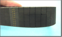
[Exterior features]
The belt is cut parallel to the teeth, and the core wires are also cut short and even.
[Probable cause]
- ① The core wire was broken due to excessive bending during storage or assembly.
- ②The pulley diameter was too small, causing the core wire to break.
[countermeasure]
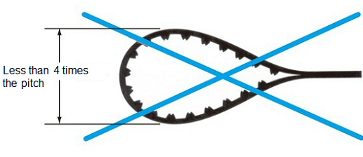
- 1. Take care when storing or assembling to avoid excessive bending. Do not bend to a diameter less than four times the pitch.
- ② Check that the diameters of Belt Sprockets and idler are appropriate. If they are too small, change them to the appropriate diameters. Check Belt Sprockets diameter in kW ratings table, and the idler diameter in the table below.
■ Idlers are used in the following cases:
- When the bearing is fixed and installation tension is adjusted
- When the speed ratio is large and the number of meshing teeth of the small pulley is increased
- When belt guides cannot be used on drive and driven pulleys
■ Precautions when using idlers
- The idler should be fixed and, in principle, used on the slack side.
- Please note that if the idler is not properly aligned, the idler will cause the belt to slip off the pulley.
- Determine the idler diameter as follows:
- Inner idler: Belt Sprockets with at least the minimum number of teeth shown in the table below.
- Outer idler: A flat pulley with no crown, with a diameter at least 1.2 times the pitch circle diameter of the pulley in the table below.
■ Minimum number of pulley teeth when selecting an idler
| kinds |
Rotational speed r/min |
| Under 900 |
Over 900
Under 1200 |
Over 1200
Under 1800 |
Over 1800
3600 or less |
| P2M |
16 |
16 |
18 |
20 |
| P3M・UP3M |
14 |
14 |
16 |
18 |
| P5M・UP5M |
18 |
20 |
24 |
28 |
| P8M・UP8M |
24 |
26 |
26 |
28 |
| P14M・UP14M |
28 |
28 |
28 |
34 |
Note: For speeds exceeding 3600 r/min, refer to the standard transmission capacity table.

Inner idler
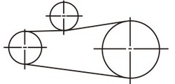
Outer idler
This can cause the rubber on the back of Synchronous Belts to crack.
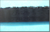
[Exterior features]
- There is a crack on the back of Synchronous Belts parallel to the teeth.
[Probable cause]
- ①The diameter of Belt Sprockets or idler being used is too small.
- ② The ambient temperature is too high or too low.
- ① Check that the diameter of Belt Sprockets and idler is appropriate. If it is too small, change it to one with the appropriate diameter.
(Check Belt Sprockets diameter in kW ratings table, and the idler diameter in the table below.)
■ Idlers are used in the following cases:
- When the bearing is fixed and installation tension is adjusted
- When the speed ratio is large and the number of meshing teeth of the small pulley is increased
- When belt guides cannot be used on drive and driven pulleys
■ Precautions when using idlers
- The idler should be fixed and, in principle, used on the slack side.
- Please note that if the idler is not properly aligned, the idler will cause the belt to slip off the pulley.
- Determine the idler diameter as follows:
- Inner idler: Belt Sprockets with at least the minimum number of teeth shown in the table below.
- Outer idler: A flat pulley with no crown, with a diameter at least 1.2 times the pitch circle diameter of the pulley in the table below.
■ Minimum number of pulley teeth when selecting an idler
| kinds |
Rotational speed r/min |
| Under 900 |
Over 900
Under 1200 |
Over 1200
Under 1800 |
Over 1800
3600 or less |
| P2M |
16 |
16 |
18 |
20 |
| P3M・UP3M |
14 |
14 |
16 |
18 |
| P5M・UP5M |
18 |
20 |
24 |
28 |
| P8M・UP8M |
24 |
26 |
26 |
28 |
| P14M・UP14M |
28 |
28 |
28 |
34 |
Note: For speeds exceeding 3600 r/min, refer to the standard transmission capacity table.
Inner idler
Outer idler
- ②Improve the ambient temperature to -15℃ to 80℃, at which point Synchronous Belts can be used.
Back to Questions
|
| Q23 |
What about wear on Belt Sprockets teeth? |
| A23 |
[Exterior features]
- The part that engages with Synchronous Belts has worn out, creating a step where it does not engage.
- The tooth surface is rough.
[Probable cause]
- 1) Belt Sprockets material is inappropriate.
- ② It was used in a dusty environment and was operated with abrasive dust adhering to Synchronous Belts and pulley.
- 3) Synchronous Belts installation tension was too high.
[countermeasure]
- 1) Change to a material with higher hardness, harden the tooth surface, or perform a surface treatment to improve wear resistance.
- ②Improve the operating environment or install a cover to prevent dust from adhering.
- 3) Adjust installation tension to the appropriate level.
Back to Questions
|
| Q24 |
How does wear on Belt Sprockets teeth affect the belt? |
| A24 |
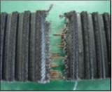
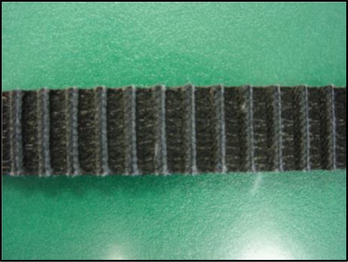
[Exterior features]
- Tooth fabric has become fuzzy, turned whitish, and the weave has become unclear.
- Tooth fabric has worn away, exposing the rubber.
- The belt teeth become thinner.
- Tooth fabric at tooth root has worn away, exposing the core wire.
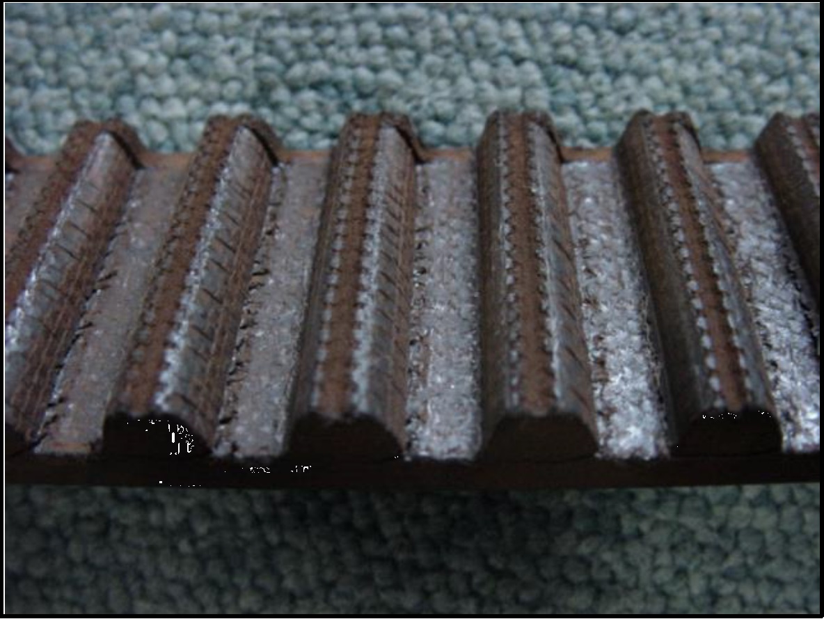
[クリックで拡大]

[クリックで拡大]
[Probable cause]
- 1) Overload occurs.
- ② Excessive installation tension.
- 3) Insufficient installation tension.
- ④Insufficient Synchronous Belts capacity.
- ⑤ Improper tooth profile or tooth dimensions of Belt Sprockets.
- ⑥ Use in a dusty atmosphere.
[countermeasure]
- (1) Check the specifications of the prime mover, the inertia of the driven machine, and the operating conditions, and eliminate the cause of the overload, or increase the size of Synchronous Belts and pulley.
- ② ③ Adjust installation tension to the appropriate level.
- 4) Check the operating conditions and select the optimum size Synchronous Belts and pulley.
- 5) Replace Belt Sprockets with one that has the correct tooth profile and dimensions.
- ⑥ Prevent dust from adhering to Synchronous Belts and pulleys by improving the atmosphere or installing a cover.
Back to Questions
|
| Q25 |
What effect does a lack of teeth have on Synchronous Belts? |
| A25 |
There is a risk of Synchronous Belts teeth skipping.
[Probable cause]
- ① Overload (shock load) occurs.
- ②Insufficient installation tension.
- 3) Insufficient number of meshing teeth with Belt Sprockets.
- ④ Insufficient rigidity of the stand.
[countermeasure]
- 1) Remove the cause of the shock load, or install a shock absorbing mechanism, or increase the size of Synchronous Belts.
- ② Adjust installation tension to the appropriate level.
- 3) Increase the number of teeth on Belt Sprockets, or install an idler to increase the number of meshing teeth.
- 4) Increase the rigidity of the stand.
Back to Questions
|
| Q26 |
What effect does Belt Sprockets misalignment and guide flange deformation have on the belt? |
| A26 |
Synchronous Belts side wear and tear
[Exterior features]
- The corners of the sides are rounded.
- The rubber on the side appears to have been ripped off.
- The core wire is frayed and exposed.
[Probable cause]
- ①Poor parallelism of the shaft.
- ② Belt Sprockets misalignment.
- 3) Insufficient rigidity of the frame.
- ④ Deformation of Belt Sprockets guide flange.
[countermeasure]
- ①Adjust the parallelism of the shaft correctly.
- ② Adjust Belt Sprockets to the correct position.
■ Pulley alignment
Even if the pulley alignment is correct, Synchronous Belts does not rotate in the center of the pulley, but tends to lean to one side.
Although this force is very weak, if the pulley is not properly aligned, the belt will be pressed hard against the pulley flange, causing damage and breakage.
Therefore, adjust the pulley alignment within the tolerances in the table below.
■ Pulley alignment tolerance
| Belt size |
All varieties |
| Belt width mm |
30 or less |
30~50 |
50~100 |
Over 100 |
| Allowable parallelism |
5/1000 or less |
4/1000 or less |
3/1000 or less |
2/1000 or less |
| θ minutes |
17 or less |
13 or less |
10 or less |
6 or less |
[Click to enlarge]
■ Pulley adjustment method
As shown in the figure, a straight edge is placed on the reference pulley, and the other pulleys are brought into contact with the entire surface of the straight edge (ε = 0), allowing the pulleys to be lined up in the correct position.
In addition, by keeping δ in the figure below the limit, it is possible to simultaneously achieve parallelism of the axis.
[Click to enlarge]
- 3) Increase the rigidity of the stand.
- ④Replace with a new one.
Back to Questions
|