technical data Top chain Selection
The latter half of this page also introduces the following selection examples:
(Click on each item to scroll to the main text.)
- *WT0700 series selection example
- *WT1500 series, WT1510 series, BTN5 type selection example
- *WT2525VG-K type selection example
- *Selection example of WT1515F-W and WT1516F-W models
- *WT3816-K type selection example
Selection example of Plastic modular chain (wide)
Step 1. Check the transport conditions
- - Transport width: approx. 600 mm
- ・Conveyor conveyor length: 10m
- ・Conveying speed: 20m/min
- ・Transported material...350ml cans (98kg/m 2)
- Accumulation...Full accumulation on conveyor
- ・Temperature... normal temperature
- ・Lubrication...soapy water lubrication
Step 2. Select the chain specifications
Low Friction / Wear resistant (LFB) specifications, open type selected
(BTO6-6096-LFB)
Step 3. Select wearstrip material
Ultra-high molecular weight polyethylene selected
(BTO6-6096-LFB)
Step 4. Calculate the tension acting on the chain
- m1 = Approximate chain mass...4kg/m
Chain width 609.6mm
6.56 (catalog value kg/m 2) x 609.6/1000 ≒ 4 (kg/m) - S1 = Length of conveying section...0m
- m2 = mass of material conveyed in the conveying section...0 kg/m
- S2 = Length of accumulator section...10m
- m3 = Mass of material conveyed in the accumulator...60 kg/m
Chain width 609.6mm
98 (kg/m 2 under the above conditions) × 609.6/1000 ≒ 60 (kg/m) - μ1 = Coefficient of dynamic friction between the chain and wearstrip...0.13 (see Table 2)
- μ2 = Friction coefficient between the chain and the conveyed object in the accumulation section...0.13 (See Table 2)
- V = Chain speed...20m/min
- η = mechanical efficiency of the drive unit...0.8
SI units (kN)
F = 9.80665 × 10⁻³ × {(2.1 × 4 + 0) × 0 × 0.13
+ (2.1 × 4 + 60) × 10 × 0.13 + 60 × 10 × 0.13} = 1.64kN
P = 1.64 × 20 60 × 0.8 = 0.683kW
Gravity Units
F = (2.1 × 4 + 0) × 0 × 0.13 + (2.1 × 4 + 60) × 10 × 0.13
+ 60 × 10 × 0.13 = 166.9kgf
P = 166.9 × 20 6120 × 0.8 = 0.682kW
Step 5. Determine chain type and width
1m width equivalent tension
F' =
1000 × 1.64
609.6
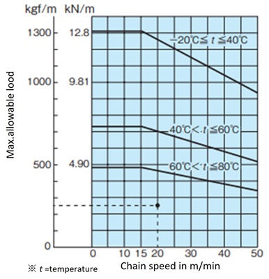
= 2.69kN/m {274kgf/m}
Usable according to Allowable load graph (please refer to each product page for Allowable load graph).
Step 6. Select the sprocket, shaft, and bearing unit
Selection of sprockets, shafts and bearing units
Bearing support span = Chain width (610) + 150 = 760mm
Graph showing the relationship between 1m width conversion capacity (F') and bearing support span, and shaft specifications and commonly used bearing units (Tables 13, 37, and 38)
10T・38 hexagonal shaft bearing unit Φ25~Φ35
or
24T・40 square shaft bearing unit Φ30~Φ35
Use one of the following:
Step 7. Calculate the tension acting on the chain
1) Check the chain tension load factor F1 (%)
F1 = 100 × 2.69 12.8 = 21.0%
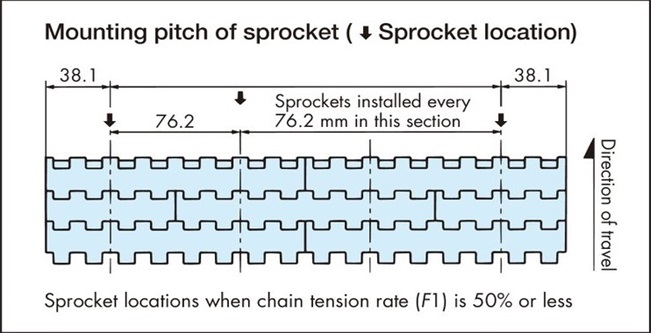
2) Determining the sprocket mounting pitch
Since F1 is less than 50%, according to (8) of Section 4-3, the sprocket should be installed at the following pitch.
WT0700 series selection example
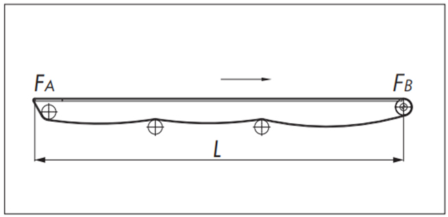
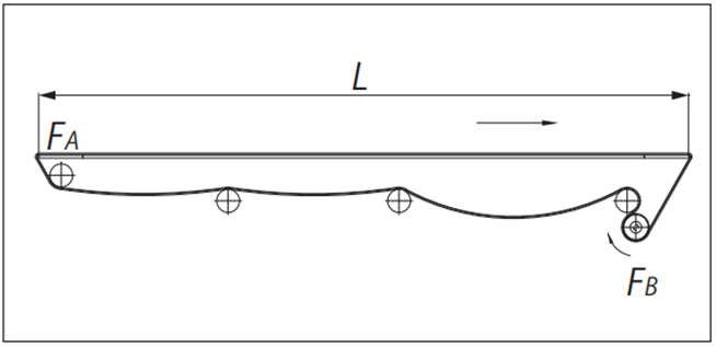
Driven side nose bar
●Calculation formula (SI unit: kN)
・ return-way tension
[A section tension: F A]
FA = m1・L・μ1・fn × 9.80665 × 10⁻³
- Transport side tension
[Tension at part B: F B]
FB = FA + {(m1 + m2) L・μ1 + m2・LS・μ2} × 9.80665 × 10⁻³
・Chain tension
F = FB
*) If there is no accumulation of transported goods, L S = 0
●Calculation example (SI units)
| Usage conditions | |
|---|---|
| Chain type | WT0705-W300-LFG (m1=5.9×0.3=1.77kg/m) |
| Chain Width | 300mm |
| Layout | L=2m |
| Chain Speed | V=15m/min |
| Transported goods | 500ml aluminum can (real) |
| Amount of material transported (per 1m length) | m2 =139kg/m 2 (523g/piece) ×0.3m=41.7kg/m |
| wearstrip | Ultra-high molecular weight polyethylene (Plastic rail) |
| Accumulation Distance | Ls=2m |
| Lubrication | dry |
| Ambient temperature | 20℃ |
| Dynamic friction coefficient between chain and wearstrip | μ1=0.2 |
| Coefficient of dynamic friction between the chain and the conveyed object | μ2=0.2 |
| Nose bar coefficient | fn=1.8 |
・ return-way tension
[A section tension: F A]
FA = 1.77 × 2 × 0.2 × 1.8 × 9.80665 × 10-3 = 0.0125kN
- Transport side tension
[Tension at part B: F B]
FB = 0.0125 + {(1.77 + 41.7) × 2 × 0.2 + 41.7 × 2 × 0.2} × 9.80665 × 10-3 = 0.35kN
・Use judgment
Maximum allowable load ≧ F B'
Convert to per 1m of chain width
FB' = 1000 × FB 300 = 1.17(kN/m)
According to Allowable load graph, allowable tension is 2.5 (kN/m)
2.5(kN/m)≧1.17(kN/m)
Selection chains are available.
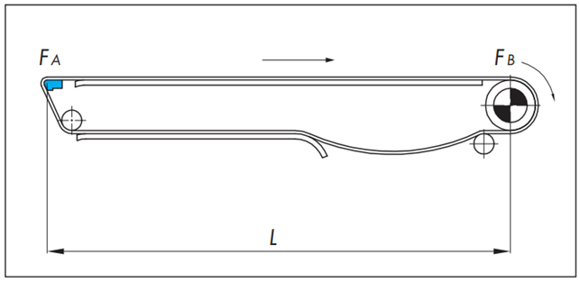
Front nose bar
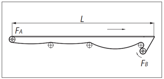
●Calculation formula (SI unit: kN)
・ return-way tension
[A section tension: F A]
FA = 1.1m1・L・μ1 × 9.80665 × 10-3
- Transport side tension
[Tension at part B: F B]
FB= [FA + {(m1 + m2) L・μ1 + m2・LS・μ2} × 9.80665 × 10⁻³] × fn
・Chain tension
F = FB
*) If there is no accumulation of transported goods, L S = 0
●Calculation example (SI units)
| Usage conditions | |
|---|---|
| Chain type | WT0705-W300-LFG (m1=5.9×0.3=1.77kg/m) |
| Chain Width | 300mm |
| Layout | L=2m |
| Chain Speed | V=15m/min |
| Transported goods | 500ml aluminum can (real) |
| Amount of material transported (per 1m length) | m2 =139kg/m 2 (523g/piece) ×0.3m=41.7kg/m |
| wearstrip | Ultra-high molecular weight polyethylene (Plastic rail) |
| Accumulation Distance | Ls=2m |
| Lubrication | dry |
| Ambient temperature | 20℃ |
| Dynamic friction coefficient between chain and wearstrip | μ1=0.2 |
| Coefficient of dynamic friction between the chain and the conveyed object | μ2=0.2 |
| Nose bar coefficient | fn=1.8 |
・ return-way tension
[A section tension: F A]
FA = 1.1 × 1.77 × 2 × 0.2 × 9.80665 × 10-3 = 0.0077kN
- Transport side tension
[Tension at part B: F B]
FB = [0.0077 + {(1.77 + 41.7) × 2 × 0.2 + 41.7 × 2 × 0.2} × 9.80665 × 10-3] × 1.8 = 0.62kN
・Use judgment
Maximum allowable load ≧ F B'
Convert to per 1m of chain width
FB' = 1000 × FB 300 = 2.07(kN/m)
According to Allowable load graph, allowable tension is 2.5 (kN/m)
2.5(kN/m)≧2.07(kN/m)
Selection chains are available.
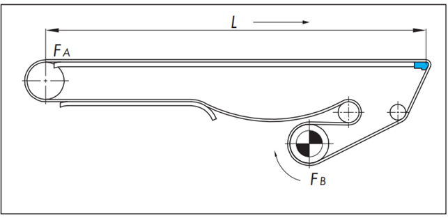
Nose bars on both ends
●Calculation formula (SI unit: kN)
・ return-way tension
[A section tension: F A]
FA = m1・L・μ1・fn × 9.80665 × 10⁻³
- Transport side tension
[Tension at part B: F B]
FB= [FA + {(m1 + m2) L・μ1 + m2・LS・μ2} × 9.80665 × 10⁻³] × fn
・Chain tension
F = FB
*) If there is no accumulation of transported goods, L S = 0
●Calculation example (SI units)
| Usage conditions | |
|---|---|
| Chain type | WT0705-W300-LFG (m1=5.9×0.3=1.77kg/m) |
| Chain Width | 300mm |
| Layout | L=2m |
| Chain Speed | V=15m/min |
| Transported goods | 500ml aluminum can (real) |
| Amount of material transported (per 1m length) | m2 =139kg/m 2 (523g/piece) ×0.3m=41.7kg/m |
| wearstrip | Ultra-high molecular weight polyethylene (Plastic rail) |
| Accumulation Distance | Ls=2m |
| Lubrication | dry |
| Ambient temperature | 20℃ |
| Dynamic friction coefficient between chain and wearstrip | μ1=0.2 |
| Coefficient of dynamic friction between the chain and the conveyed object | μ2=0.2 |
| Nose bar coefficient | fn=1.8 |
・ return-way tension
[A section tension: F A]
FA = 1.77 × 2 × 0.2 × 1.8 × 9.80665 × 10-3 = 0.0125kN
- Transport side tension
[Tension at part B: F B]
FB = [0.0125 + {(1.77 + 41.7) × 2 × 0.2 + 41.7 × 2 × 0.2} × 9.80665 × 10-3] × 1.8 = 0.63kN
・Use judgment
Maximum allowable load ≧ F B'
Convert to per 1m of chain width
FB' = 1000 × FB 300 = 2.1(kN/m)
According to Allowable load graph, allowable tension is 2.5 (kN/m)
2.5(kN/m)≧2.1(kN/m)
Selection chains are available.
f n (nose bar coefficient)
| Lubrication status | Nose bar coefficient fn |
|---|---|
| Sliding Type | |
| dry | 1.8 |
| soapy water | 1.35 |
WT1500 series, WT1510 series, BTN5 type selection example
Driven side nose bar
●Calculation formula (SI unit: kN)
・ return-way tension
[A section tension: F A]
FA = m1・L・μ1・fn × 9.80665 × 10⁻³
- Transport side tension
[Tension at part B: F B]
FB = FA + {(m1 + m2) L・μ1 + m2・LS・μ2} × 9.80665 × 10⁻³
・Chain tension
F = FB
*) If there is no accumulation of transported goods, L S = 0
●Calculation example (SI units)
| Usage conditions | |
|---|---|
| Chain type | WT1506-K30-ALF (m1=6.7×0.762=5.1kg/m) |
| Chain Width | 762mm |
| Layout | L=4m |
| Chain Speed | V=15m/min |
| Transported goods | 500ml aluminum can (real) |
| Amount of material transported (per 1m length) | m 2 =139kg/m 2 (523g/piece) ×0.762m=106kg/m |
| wearstrip | Ultra-high molecular weight polyethylene (Plastic rail) |
| Accumulation Distance | Ls=4m |
| Lubrication | dry |
| Ambient temperature | 20℃ |
| Dynamic friction coefficient between chain and wearstrip | μ1=0.15 |
| Coefficient of dynamic friction between the chain and the conveyed object | μ2=0.14 |
| Nose bar coefficient | fn=1.35 (bearing roller type) |
・ return-way tension
[A section tension: F A]
FA = 5.1 × 4 × 0.15 × 1.35 × 9.80665 × 10-3 = 0.04kN
- Transport side tension
[Tension at part B: F B]
FB = 0.04 + {(5.1 + 106) × 4 × 0.15 + 106 × 4 × 0.14} × 9.80665 × 10-3 = 1.28kN
・Use judgment
Maximum allowable load ≧ F B'
Convert to per 1m of chain width
FB' = 1000 × FB 762 = 1.68(kN/m)
According to Allowable load graph, allowable tension is 10.5 (kN/m)
10.5(kN/m)≧1.68(kN/m)
Selection chains are available.
Front nose bar
●Calculation formula (SI unit: kN)
・ return-way tension
[A section tension: F A]
FA = 1.1m1・L・μ1 × 9.80665 × 10-3
- Transport side tension
[Tension at part B: F B]
FB= [FA + {(m1 + m2) L・μ1 + m2・LS・μ2} × 9.80665 × 10⁻³] × fn
・Chain tension
F = FB
*) If there is no accumulation of transported goods, L S = 0
●Calculation example (SI units)
| Usage conditions | |
|---|---|
| Chain type | WT1506-K30-ALF (m1=6.7×0.762=5.1kg/m) |
| Chain Width | 762mm |
| Layout | L=4m |
| Chain Speed | V=15m/min |
| Transported goods | 500ml aluminum can (real) |
| Amount of material transported (per 1m length) | m 2 =139kg/m 2 (523g/piece) ×0.762m=106kg/m |
| wearstrip | Ultra-high molecular weight polyethylene (Plastic rail) |
| Accumulation Distance | Ls=4m |
| Lubrication | dry |
| Ambient temperature | 20℃ |
| Dynamic friction coefficient between chain and wearstrip | μ1=0.15 |
| Coefficient of dynamic friction between the chain and the conveyed object | μ2=0.14 |
| Nose bar coefficient | fn=1.35 (bearing roller type) |
・ return-way tension
[A section tension: F A]
FA = 1.1 × 5.1 × 4 × 0.15 × 9.80665 × 10-3 = 0.03kN
- Transport side tension
[Tension at part B: F B]
FB = [0.03 + {(5.1 + 106) × 4 × 0.15 + 106 × 4 × 0.14} × 9.80665 × 10-3] × 1.35 = 1.71kN
・Use judgment
Maximum allowable load ≧ F B'
Convert to per 1m of chain width
FB' = 1000 × FB 762 = 2.24(kN/m)
According to Allowable load graph, allowable tension is 10.5 (kN/m)
10.5(kN/m)≧2.24(kN/m)
Selection chains are available.
Nose bars on both ends
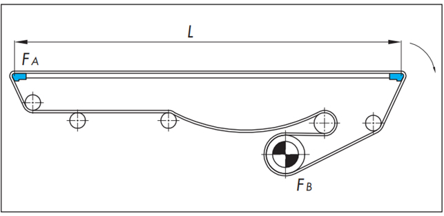
●Calculation formula (SI unit: kN)
・ return-way tension
[A section tension: F A]
FA = m1・L・μ1・fn × 9.80665 × 10⁻³
- Transport side tension
[Tension at part B: F B]
FB= [FA + {(m1 + m2) L・μ1 + m2・LS・μ2} × 9.80665 × 10⁻³] × fn
・Chain tension
F = FB
*) If there is no accumulation of transported goods, L S = 0
●Calculation example (SI units)
| Usage conditions | |
|---|---|
| Chain type | WT1506-K30-ALF (m1=6.7×0.762=5.1kg/m) |
| Chain Width | 762mm |
| Layout | L=4m |
| Chain Speed | V=15m/min |
| Transported goods | 500ml aluminum can (real) |
| Amount of material transported (per 1m length) | m 2 =139kg/m 2 (523g/piece) ×0.762m=106kg/m |
| wearstrip | Ultra-high molecular weight polyethylene (Plastic rail) |
| Accumulation Distance | Ls=4m |
| Lubrication | dry |
| Ambient temperature | 20℃ |
| Dynamic friction coefficient between chain and wearstrip | μ1=0.15 |
| Coefficient of dynamic friction between the chain and the conveyed object | μ2=0.14 |
| Nose bar coefficient | fn=1.35 (nose bar roller type) |
・ return-way tension
[A section tension: F A]
FA = 5.1 × 4 × 0.15 × 1.35 × 9.80665 × 10-3 = 0.04kN
- Transport side tension
[Tension at part B: F B]
FB = [0.04 + {(5.1 + 106) × 4 × 0.15 + 106 × 4 × 0.14} × 9.80665 × 10-3] × 1.35 = 1.72kN
・Use judgment
Maximum allowable load ≧ F B'
Convert to per 1m of chain width
FB' = 1000 × FB 762 = 2.26(kN/m)
According to Allowable load graph, allowable tension is 10.5 (kN/m)
10.5(kN/m)≧2.26(kN/m)
Selection chains are available.
f n (nose bar coefficient)
| Lubrication status | Nose bar coefficient fn | |
|---|---|---|
| Sliding Type | Bearing/roller type | |
| dry | 1.8 | 1.35 |
| soapy water | 1.35 | |
WT2525VG-K type selection example
Forward/reverse bottom drive selection example
●Calculation formula (SI unit: kN)
-return-way tension (follower side)
[A section tension: F A]
FA = 1.1m1・L1・μ1 × 9.80665 × 10-3
- Transport side tension
[Tension at part B: F B]
FB = 1.1{FA + (m1 + m2) × L・μ1 × 9.80665 × 10-3}
-return-way tension (drive side)
[C part tension: F C]
FC = FB + m1・L2・μ1 × 9.80665 × 10-3
・Chain tension
F = FC
●Calculation example (SI units)
| Usage conditions | |
|---|---|
| Chain type | WT2525VG-K36-G (m1=9.5×0.9144=8.7kg/m) |
| Chain Width | 914.4mm |
| Layout | L=10m, L1=6m, L2=4m |
| Chain Speed | V=10m/min |
| Transported goods | Cardboard sheet 900mm x 1800mm x 5mm 106.4 kg/m 2 = 861.8 g/sheet x 200 sheets (height 1 m) |
| Amount of material transported (per 1m length) | m2=106.4kg/m2×0.9144m =97.3kg/m |
| wearstrip | Ultra-high molecular weight polyethylene (Plastic rail) |
| Lubrication | dry |
| Ambient temperature | 20℃ |
| Dynamic friction coefficient between chain and wearstrip | μ1=0.25 |
-return-way tension (follower side)
[A section tension: F A]
FA = 1.1 × 8.7 × 6 × 0.25 × 9.80665 × 10-3 = 0.14kN
- Transport side tension
[Tension at part B: F B]
FB = 1.1 {0.14 + (8.7 + 97.3) × 10 × 0.25 × 9.80665 × 10-3} = 3.0kN
-return-way tension (drive side)
[C part tension: F C]
FC = 3.0 + 8.7 × 4 × 0.25 × 9.80665 × 10-3 = 3.09kN
・Use judgment
Maximum allowable load ≧ F B'
Convert to per 1m of chain width
FB' = 1000 × FB 914.4 = 3.34(kN/m)
According to Allowable load graph, allowable tension is 12.8 (kN/m)
12.8(kN/m)≧3.34(kN/m)
Selection chains are available.
WT1515F-W and WT1516F-W selection examples
Calculation of inclined conveyance (horizontal + inclined + horizontal)
Basically, it is the same as for inclined conveyance (inclined only). The tension acting on the curved section between horizontal and inclined is corrected by the angle coefficient.
A calculation example is shown for the transport route shown below.

●Calculation formula (SI unit: kN)
L2 = r × αS L4 = r × αS
・ return-way tension
[A section tension: F A]
FA = m1(L1 + L2) μ1・αL × 9.80665 × 10⁻³
L2 = r × αS
[Tension at part B: F B]
F B = F A + m1 (L h3 ・ μ1-L v3) × 9.80665 × 10-3
If
F B < 0, then F B = 0
[C part tension: F C]
FC = 1.1 × (FB + m1(L4 + L5)) × 9.80665 × 10⁻³・αL
L4 = r × αS
- Transport side tension
[D part tension: F D]
FD = {FC + (m1 + m2)(L4 + L5) μ1} × 9.80665 × 10⁻³・αL
L4 = r × αS
[Tension at E section: F E]
FE = FD + (m1 + m2)(Lh3・μ1 + Lv3) × 9.80665 × 10-3
[F part tension: F F]
FF = {FE + (m1 + m2)(L1 + L2) μ1} × 9.80665 × 10⁻³・αL
L2 = r × αS
・Chain tension
F = FF
Force acting on float-preventive tabs
When attaching float-preventive tabs to the chain, calculate the force Ft that will be applied to one point on float-preventive tabs.
The chain lifts up at the curved section between horizontal and inclined. The lifting force is greatest at L4.
Ft = FD sin θ/2 nt × 1000
n t = L4 Total number of float-preventive tabs
n t = L 4 30 × (number of tabs knitted in the chain width direction)
float-preventive tabs Can be used if the force Ft applied to one point is 240N or less.
Ft < 240N
●Calculation example (SI units)
| Usage conditions | |
|---|---|
| Chain type | WT1515T-F-W400-LFG-10L-FM50N2 (m 1 =6.7×0.4=2.7kg/m) |
| Chain Width | 400mm |
| Layout | L 1 =0.7m L v3 =1.5m L h3 =0.866m L5 =0.7m r=0.5m, angle 60°, length coefficient αs=1.0 L 2 =L 4 =0.5×1.0=0.5m (lifting height 2m) |
| Tilt angle | θ=60° |
| Chain Speed | V=9m/min |
| Transported goods | Aluminum parts, 20mm cube, 120 pieces in one location stir-fry |
| Amount of material transported (per 1m length) | m 2 =30kg/m 2 (15g/piece)×0.4m =12kg/m |
| wearstrip | Ultra-high molecular weight polyethylene (Plastic rail) |
| Accumulation Distance | Ls=4m |
| Lubrication | dry |
| Ambient temperature | 20℃ |
| Dynamic friction coefficient between chain and wearstrip | μ 1 =0.2 (angle coefficient αL=1.25) |
・ return-way tension
[A section tension: F A]
FA = 2.7 (0.7 + 0.5) 0.2 × 1.25 × 9.80665 × 10-3
[Tension at part B: F B]
F B = 0.0079 + 2.7 (0.866 × 0.2 - 1.5) × 9.80665 × 10-3 = -0.027kN
Since
F B < 0, F B = 0kN
[C part tension: F C]
FC= 1.1 × (0 + 5.1(0.5 + 0.7)) 1.25 × 9.80665 × 10-3・αL = -0.083kN
- Transport side tension
[D part tension: F D]
FD={0.083 + (2.7 + 12)(0.5 + 0.7) 0.2 × 9.80665 × 10-3} × 1.25 = 0.15kN
[Tension at E section: F E]
FE = 0.15 + (2.7 + 12)(0.866 × 0.2 + 1.5) × 9.80665 × 10-3 = 0.39kN
[F part tension: F F]
FF = {0.39 + (2.7 + 12)(0.7 + 0.5) 0.2 × 9.80665 × 10-3・αL = 0.53kN
・Chain tension
F = 0.53kN
・Use judgment
Maximum allowable load ≧ F
F' = 1000 × F 400 = 1.3(kN/m)
According to Allowable load graph, allowable tension is 10.5 (kN/m)
10.5(kN/m)≧1.3(kN/m)
Selection chains are available.
- Force acting on float-preventive tabs
Ft = 0.15 × sin(60/2) 13 × 1000 = 5.8kN
n t = 400 30 = 13 locations
The force applied to one tab float-preventive tabs is 5.8N.
It is usable because it is 5.8N < 240N.
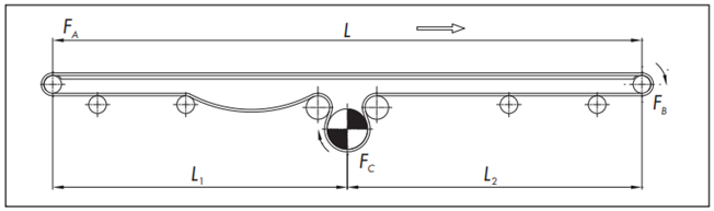
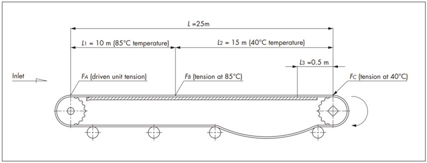
WT3816-K type selection example
Special conveyors (pasteurizers/warmers/coolers)
●Calculation formula (SI unit: kN)
・ return-way tension
[A section tension: F A]
FA = 1.1m1・L・μ1 × 9.80665 × 10-3
- Transport side tension
[Tension at part B: F B]
FB = FA + (m1 + m2) L1・μ1 × 9.80665 × 10-3
[C part tension: F C]
FC = FB + {(m1 + m2) L2・μ1 + m2・L3・μ2} × 9.80665 × 10⁻³
●Calculation example (SI units)
| Usage conditions | |
|---|---|
| Chain type | WT3816-K2000-HTW (m1=9.8×2=19.6kg/m) |
| Chain Width | 2000mm |
| Layout | L=25m, L1=10m, L2=15m |
| Chain Speed | V=1m/min |
| Transported goods | 1500ml plastic bottle (real) |
| Amount of material transported (per 1m length) | m 2 =200kg/m 2 (1530g/piece)×2m =400kg/m |
| wearstrip | Stainless steel (polished) |
| Accumulation Distance | L3=0.5m |
| Lubrication | Water (warm water) |
| Ambient temperature | Warm water (maximum 85°C) |
| Dynamic friction coefficient between chain and wearstrip | μ1=0.35 |
| Coefficient of dynamic friction between the chain and the conveyed object | μ2=0.35 |
・ return-way tension
[A section tension: F A]
FA = 1.1 × 19.6 × 25 × 0.35 × 9.80665 × 10-3 = 1.85kN
- Transport side tension
[Tension at part B: F B]
FB = 1.85 + (19.6 + 400) × 10 × 0.35 × 9.80665 × 10-3 = 16.3kN
[C part tension: F C]
FC = 16.3 + {(19.6 + 400) × 15 × 0.35 + 400 × 0.5 × 0.35} × 9.80665 × 10-3 = 38.6kN
・Use judgment
Judgment is made in each temperature range
Maximum allowable load ≧ F
・At 85℃
Working tension F = F B'
Convert to per 1m of chain width
FB' = 1000 × FB 2000 = 8.15(kN/m)
According to Allowable load graph, allowable tension at 85°C is 8.3 (kN/m)
8.3(kN/m)≧8.15(kN/m)
Selection chains are available.
・When the temperature is 40℃
Working tension F = F C'
Convert to per 1m of chain width
FC' = 1000 × FC 2000 = 19.3(kN/m)
According to Allowable load graph, allowable tension at 40°C is 20 (kN/m)
20(kN/m)≧19.3(kN/m)
Selection chains are available.
Can be used in all temperature ranges.

