technical data Top chain Selection
This page introduces the following items:
(Click on each item to scroll to the main text.)
- 2-1. Rail placement
- 2-2. Guide clearance
- 2-3. Example of installation of wearstrip (at room temperature)
- 2-4. Conveyor layout
- 2-5. WT0700 series double nose bar installation example
- 2-6. Installation example of WT1500 series and BTN5 with double nose bars
- 2-7. WT2520 series forward/reverse bottom drive layout
- 2-8. Nose bar in-line layout
- 2-9. BTC4-M type in-line joint layout
- 2-10. WT2520 series in-line layout
- 2-11. Orthogonal transport layout
- 2-12. Orthogonal transport of WT1500 and WT1505G
- 2-13. Inclined conveyor take-up
- 2-14. return-way of flight type chain
- 2-15. Special organization of float-preventive tabs
- 2-16. Transfer plate installation
Plastic modular chain (Wide) Conveyor Design Information
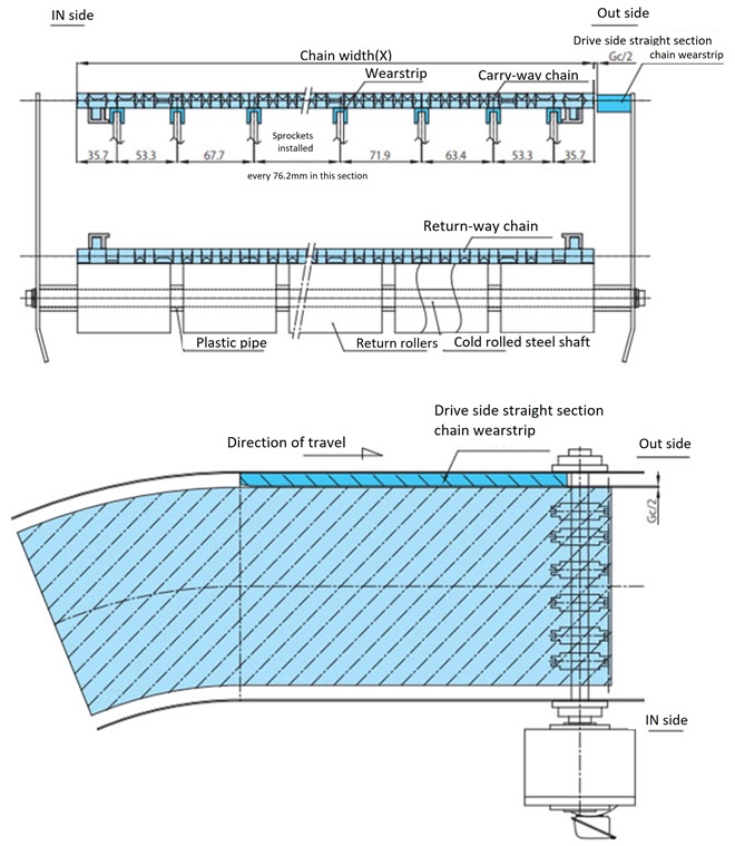
2-1. Rail placement
The rail layout will vary depending on the installation space, but an example is shown in the diagram below (heavy load layout).
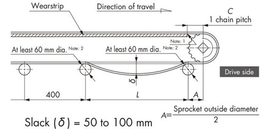
Note)
- 1. Chamfer wearstrip and frame end faces of the drive sprocket to prevent interference.
- 2. WT1907, WT3827, and WT5707 are Φ80 or larger.
- 3. WT0705-W, WT1515-W, WT1516-W, WT0705-M, WT1515G-M, and BTC4-M types are Φ20 or larger.
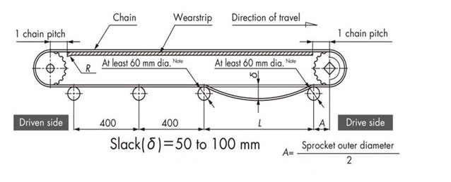
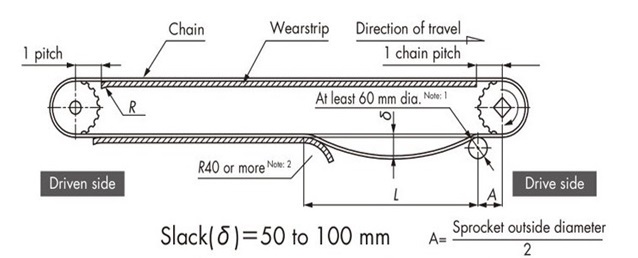
2-1-1. Chain slack
Refer to Table 5 below for the distance L between the return rollers that receive return-way chain under the drive sprocket, and keep the chain slack between the return rollers at 50 to 100 mm. This slack prevents tooth skipping. Tooth skipping may occur if the chain is outside this range.
Table 5. Return roller spacing L
| Chain type | Return roller spacing L | |
|---|---|---|
| Tension load factor (F1) | ||
| When it is below 50% | When it exceeds 50% | |
| WT0405, WT0705 | 400 ~ 600 | |
| BT6, BT8 | 500 ~ 700 | 800 ~ 1000 |
| WT2250, WT2515, WT2525, WT2525VG | 600 ~ 900 | |
| WT1500, 2500, 3000, 3800 | 450 ~ 500 | |
| WT3109, BTH16 | 750 ~ 1000 | |
For WT1907, WT3827, WT3835, and WT5707
| Transport conditions | Roller spacing L |
|---|---|
| For conveyor length of less than 12m and transport loads of 75kg/m2 or less | 600 ~ 900 |
| For conveyor length of less than 20m and transport loads of 100kg/m2 or less | 750 ~ 900 |
| When conveyor length is less than 20m and the amount of material being transported exceeds 100kg/m 2 | 1200 ~ 1500 |
Note)
- 1. mold-to-width types should be designed in the same way as Plastic top chain.
- 2. Please contact us regarding special conveyors such as pasteurizers.
- 3. Please refer to the installation of the nose bars on both ends.
For WT0705-W, WT1515/6-W, WT0705-M, WT1515G-M, and BTC4-M models
| Return roller | Recommended chain width | Return roller center distance |
|---|---|---|
| TP-RR20650 | 300mm or less | 400mm |
| TP-RR30850 | 500mm or less | 400 ~ 600mm |
| TP-RR41050 | 600mm or less |
2-1-2. Engagement angle
The meshing angle between the drive sprocket and chain must be at least 180° Note. If the angle is too small, teeth may skip.
Note) The bottom drive "engagement angle" is 200° or more.
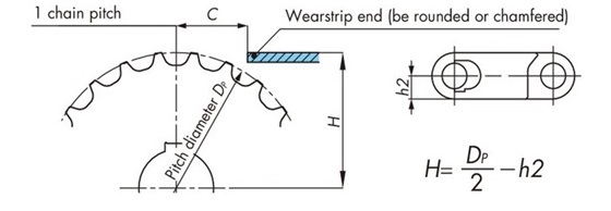
2-1-3.Running wearstrip end
The distance C between the sprocket and the end of wearstrip should be one basic chain pitch.
In addition, the end of the driven wearstrip should be bent or chamfered to prevent the chain from getting caught wearstrip.
2-1-4. Sprocket and wearstrip position
Please refer to the diagram below.
Note: Please contact us regarding the WT3109-W and BTH16 types.
Table 6. Backbend Radius
| Chain type | Backbend Radius R mm |
|
|---|---|---|
| Wide | WT0405-W | 5 |
| WT0705-W | 10 | |
| BTN5, WT1505-K, WT1505RN-K, WT1505G-K, WT1505GTO-K, WT1505GTORN-K, WT1506-K, WT1515-W, WT1515G-W, WT1515VG-W, WT1516-W, WT1515G-M, BTC6, BTC6RN, BTC6-T, BTC6RN-T, BTO6, BTO6RN, BTN6 |
15 | |
| WT1907-K | 90 | |
| BTC8, BTM8H, WT2250-W, WT2525-K, WT2515-W, WT2515G-W |
25 | |
| WT2505-K, WT2506-K, WT2706-K, WTU3015T-K |
20 | |
| WT2525VG-K, WT2705-K, WT3005-K, WT3005G-K, WT3086-K, WT3086G-K |
30 | |
| WT3109-W | 35 | |
| WT3816-K, WT3835-K | 40 | |
| WT3827-K | 50 | |
| BTH16 | 60 | |
| WT5707-K | 70 | |
| mold-to-width | BTC4-M, WT0705-M | 10 |
| WT1505G-M, WT1505GTO-M, WT1505TOD-M, WT1515G-M |
15 | |
| BTO8-M, WT2505-M, WT2505G-M, WT2505TOD-M, WTM2535G-M |
20 | |
| BTC8H-M, BTM8H-M, WT2515G-M, WT2525-M |
25 | |
| WT2525VG-M, WT3005G-M, WT3086G-M, WT3085-C325 |
30 | |
| WT3835G-M | 40 | |
Note: For flight types, this varies depending on the flight configuration and height.
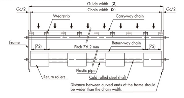
2-2. Guide clearance
Considering thermal expansion, the guide clearance between the chain and guide channel should be set to the following dimensions.
Conveyor guide width (G) = chain width (X) + guide clearance (Gc)
Table 7. Guide clearance Gc
| Chain width mm | Temperature ℃ | ||
|---|---|---|---|
| -20 ~ 40 | 40 ~ 60 | 60 ~ 80 | |
| Under 300 | 5.0 | 6.0 | 7.0 |
| Over 300 to 500 | 6.0 | 7.0 | 9.0 |
| Over 500 to under 1000 | 8.0 | 11.0 | 15.0 |
| Over 1000 to 1500 | 11.0 | 15.0 | 21.0 |
| Over 1500 to 2000 | 14.0 | 20.0 | 28.0 |
| Over 2000 to 2500 | 17.0 | 24.0 | 34.0 |
| Over 2500 to 3000 | 19.0 | 27.0 | 40.0 |
Note) Linear expansion coefficient of polyacetal chain: 12 × 10-5 /℃
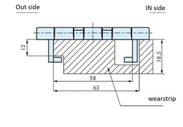
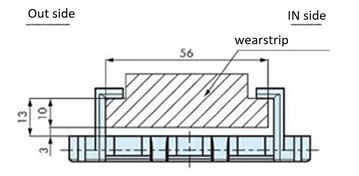
2-3. Example of installation of wearstrip (at room temperature)
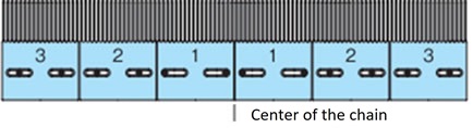
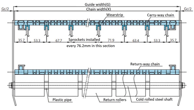
2-3-1. Wide type (without anti-snake attachment)
wearstrip and sprockets should be arranged alternately and at equal intervals.
wearstrip spacing is 45mm for the WT0400 series, 50mm for the WT0700 series and WT1510, 50.8mm for the WT1907, 76mm for the BTN5, 76.2mm (rail width 25mm) for the BT6, BT8, WT1500 series, WT3005, WT3835, and WT2500 series, 85mm for the WT3086, WT2515, and WT2250, 100mm (rail width 30mm) for the WT3816, and 152.4mm for the WT3827 and WT5707.
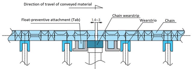
2-3-2. Wide type (with anti-snake attachment (tab))
(Chains with anti-snake attachments (tabs): BTN5-A, WT1505G-K, WT1515G-W, WT1505GTO-K, WT1505GTORN-K, WT2515G-W, WT3005G-K, WT3086G-K, BTC8-A)
Install the anti-snake attachment (tab) so that it does not interfere with wearstrip.
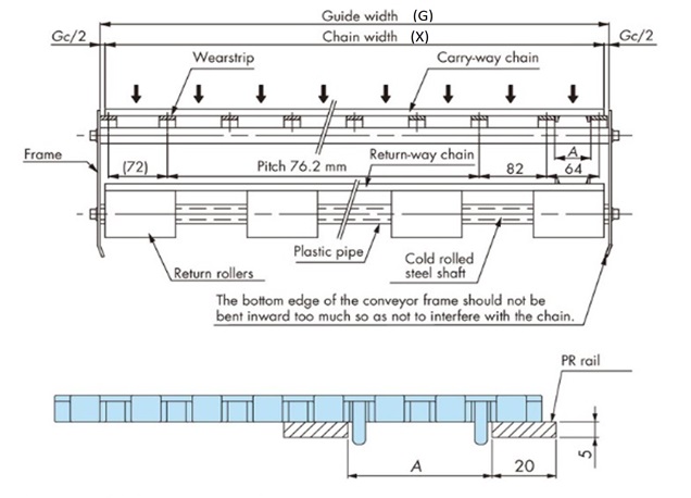
Table 8. A dimension list (wide type (with anti-snake attachment (tab)))
| Chain type | A |
|---|---|
| WT1505G-K | 44 |
| WT1505GTO-K, WT1505GTORN-K | 47 |
| BTN5-A | 44 |
| WT2515G-W | 45 |
| BTC8-A | 44 |
| WT3005G-K | 44 |
| WT3086G-K | 44 |
| WT1515G-W | 31 |
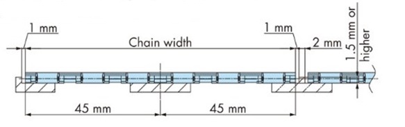
2-3-3. Wide type (WT0405-W type)
When using multiple strand, make sure the chains do not come into contact with each other on their sides. An example is shown in the diagram below.
2-3-4. Wide type (WTU3015T-K type)
・Layout on straight sections
wearstrip and sprockets should be arranged alternately and at equal intervals.
1) Example of wearstrip installation
3) Parallel passing layout (wrap)
When transferring parallel chains on a straight section, install guide channel along the side of the upstream chain float-preventive tabs.
2) Layout of the straight section on the drive side
Install a chain guide channel on the OUT side of the straight section on the drive side of a curved conveyor.
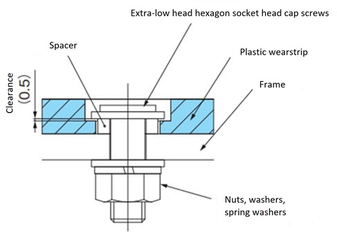
2-3-5. Wide type (for WT3109-W/BTH16)
Please refer to the example below. Instead of completely fixing the rail to the frame with bolts, use spacers to create a gap and fix the resin rail in place to prevent it from floating due to differences in thermal expansion.
2-3-6. mold-to-width type (with anti-snake attachment (tab))
Refer to the table below for guide clearance for chains with anti-snaking attachments (tabs). When using multiple strand, leave a gap of about 1 mm between the chains.
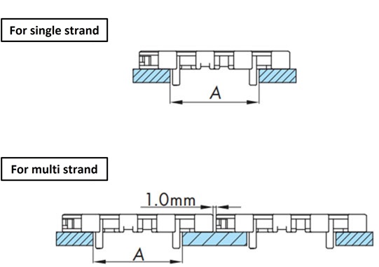
Table 9. A dimension list
(mold-to-width type (with anti-snake attachment (tab)))
| Chain type | A |
|---|---|
| WT1505G-M | 44 |
| WT1505GTO-M | 47 |
| WT1505TOD | 53 |
| WT1515G-M50 | 31 |
| WT1515G-M100 | 61 |
| WT2505G-M | 45 |
| WT2505TOD | 45 |
| WT2515G-M | 45 |
| WTM2535G-M | 44 |
| WT3005G-M | 44 |
| WT3086G-M | 44 |
| WT3835G-M | 45 |
| BTO8-M | 44 |
| BTC8H-M | 44 |
| BTM8H-M | 44 |
2-3-7. Heat-resistant and high-speed (KV) wearstrip installation
- ・We recommend using stainless steel for wearstrip material.
- - When fixing wearstrip, fix only one end, taking thermal expansion into consideration. Also, take thermal expansion into consideration when determining the gap between wearstrip.
- ・Take-up is required to absorb thermal expansion of the chain. Always adjust the take-up after raising the chain to operating temperature.
When lowering the temperature, be sure to loosen the take-up first. - - Black Wear debris will be generated. Clean regularly.
2-4. Conveyor layout
There are two types of receiving methods on return-way: "return roller receiving method" and "wearstrip receiving method." Examples are shown below.
*Notes
- 1. Please be especially careful when making transfers at end, such as by TOD.
- 2. The entrance of the return wearstrip should have a large radius of R40 or more.
- 3. Chains expand and contract due to temperature changes, so trim the chain so that there is an appropriate amount of slack in the catenary section, and adjust it using a tensioner or similar device.
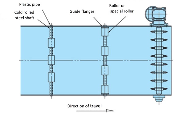
2-4-1. Return roller receiving method
Adjust the roller installation interval (conveyor width direction) to match the width of the chain being used.
(Conveyor side) (Heavy load layout)
Note)
- WT1907, WT3827, and WT5707 are Φ80 or larger.
For L dimensions, refer to Table 5 above.
(Conveyor return-way flat surface)
2-4-2. Supporting method on wearstrip
(Conveyor side) (Heavy load layout)
Note)
- 1. WT1907, WT3827, and WT5707 are Φ80 or larger.
- 2. WT1907, WT3827, and WT5707 are back bend radius or larger.
For L dimensions, refer to Table 5 above.
2-4-3. Layout for curved sections (WTU3015T-K type)
For curved conveyance, please ensure that there is a straight section of at least 800 mm between the drive unit and the curved section to ensure a catenary return-way.
1) Example of wearstrip installation

2) Processing of the entrance and exit of wearstrip
The entrance and exit sections of the curved wearstrip where it transfers to the straight wearstrip should be chamfered to prevent the chain from getting caught.

・Layout on return-way curve
On both ends of return-way curved rail, install return rollers or sliding shoes (TP-C14343T-SD) 50 mm away from the rail to guide the chain.
Conveyor side cross section

2-4-4. Layout for curved sections (WT3085-C type)
Installation of wearstrip on the curved section of the conveying side
Installing wearstrip on the return-way curve
(Attachment sliding)
(top plate sliding)
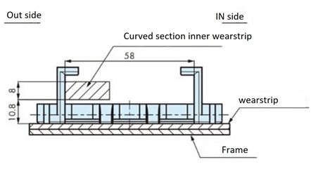
2-5. WT0700 series double nose bar installation example
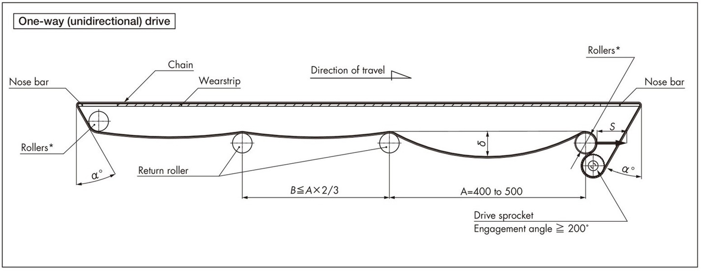
Points to note when designing conveyors
- 1. *Please use a take-up type roller.
- - It becomes easier to absorb chain elongation, cutting and connecting, and adjust slack (δ).
- ・The guideline for take-up stroke (S) is S = conveyor length × 1%
- 2. *About the roller part
- - Select an outer diameter that is as large as possible, at least Φ50.
- - The shaft used must have sufficient rigidity.
- ・Make sure to rotate it.
- 3. Chains expand and contract due to temperature changes, so either splice the chain or adjust it with a tensioner so that the catenary section has the appropriate slack.
[Reference: Linear expansion coefficient of polyacetal chain: 12 × 10-5 /℃]
- 4. When using forward/reverse bottom drive, the roller section is subjected to a load approximately 1.5 times the operating tension. For wide conveyors (over 1m), select a shaft with sufficient rigidity or ensure that the shaft is supported at three or more points.
Precautions when using nose bars
- 1. The bracing used to attach the nose bar should be rigid, and sag should be kept to within 0.5 mm.
- 2. The tolerance for frame bending and twisting in the conveyor width direction must be within 0.3 mm.
- 3. Set the position dimensions of the nose bar and the roller and sprocket so that the angle α is 30° or less.
- 4. The nose bar slides against the chain at a load close to the maximum operating tension, so we recommend SJ-CNO (special polyamide) for dry conditions, high-speed travel, and heavy load transportation.
Note: This design document is based on specifications that take heavy load conditions into account.
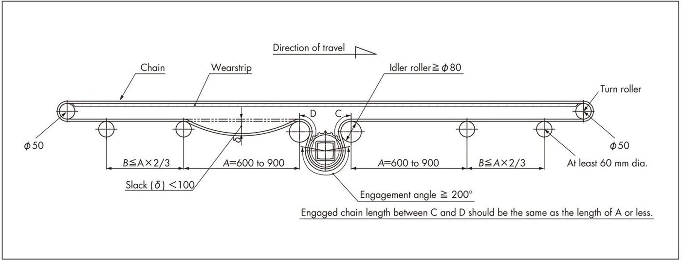
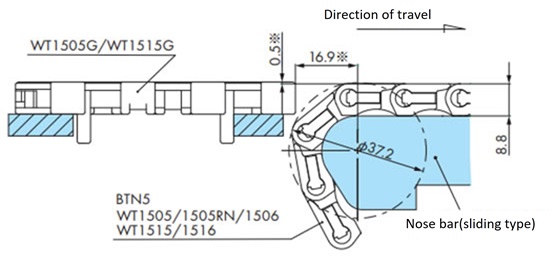
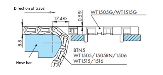
2-6. Installation example of WT1500 series and BTN5 with double nose bars
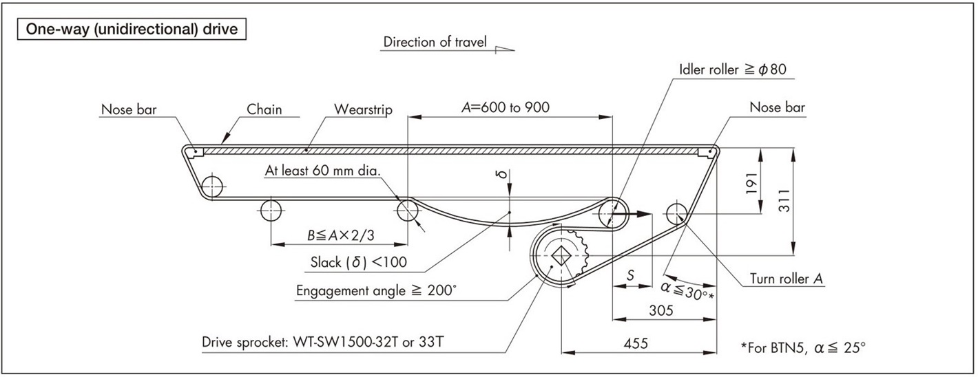

Points to note when designing conveyors
- 1. Idler rollers should be of the take-up type.
- - It becomes easier to absorb chain elongation, cutting and connecting, and adjust slack (δ).
- ・The guideline for take-up stroke (S) is S = conveyor length × 1%
- 2. Select an idler roller with an outer diameter of Φ80 or larger.
- 3. Be sure to rotate the idler rollers.
- 4. The shaft used for Turn Roller A and Turn Roller must have sufficient rigidity. (Do not use high-speed return rollers as Turn Rollers.)
- 5. The chain expands and contracts due to temperature changes, so either splice the chain or adjust it with a tensioner so that the catenary section has the appropriate slack.
[Reference: Linear expansion coefficient of polyacetal chain: 12 × 10-5 /℃]
- 6. When using forward/reverse bottom drive, the idler roller is subjected to a load approximately 1.5 times the operating tension. For wide conveyors (over 1m), select a shaft with sufficient rigidity or ensure that the shaft is supported at three or more points.
Precautions when using nose bars
- 1. The bracing used to attach the nose bar should be rigid, and sag should be kept to within 0.5 mm.
- 2. The tolerance for frame bending and twisting in the conveyor width direction must be within 0.3 mm.
- 3. Set the position dimensions of the nose bar and turn roller so that the angle α is 30° or less.
- 4. The nose bar slides against the chain at a load close to the maximum operating tension, so for dry conditions, high-speed travel, and heavy load transport, we recommend material grades PLF or SJ-CNO (special polyamide).
Note: This design document is based on specifications that take heavy load conditions into account.
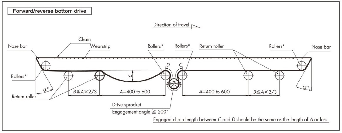
2-7. WT2520 series forward/reverse bottom drive layout
Points to note when designing conveyors
- 1. Select an idler roller with an outer diameter of Φ80 or larger.
- 2. Be sure to rotate the idler rollers.
- 3. The shaft used for the turn roller must have sufficient rigidity. (Do not use high-speed return rollers as the turn roller.)
- 4. Chains expand and contract due to temperature changes, so either splice the chain or adjust it with a tensioner so that the catenary section has the appropriate slack.
[Reference: Linear expansion coefficient of polyacetal chain: 12 × 10-5 /℃]
- 5. When using forward/reverse bottom drive, the idler roller is subjected to a load approximately 1.5 times the operating tension. For wide conveyors (over 1m), select a shaft with sufficient rigidity or ensure that the shaft is supported at three or more points.
2-8. Nose bar in-line layout
2-8-1. WT0405-W type in-line layout
By using a 2.5mm R nose bar, conveyors can in-line together in a layout.
It is possible to narrow it down to 13 mm without using the dead plate that was previously required.
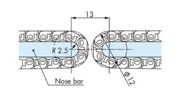
Note: Please contact us for details.
2-8-2. WT0700 series in-line layout
・WT0700 series nose bar in-line layout
It is possible to in-line conveyors in a straight butt joint.
It is possible to narrow the gap to a minimum by using a dead plate.
・WT0700 series nose bar and sprocket in-line layout
Connections between conveyors can be in-line with sprockets.
It is possible to narrow the gap to a minimum by using a dead plate.

・WT0700 series nose bar and WT1500 series sprocket in-line layout
Connections between conveyors can be in-line with sprockets.
It is possible to narrow the gap to a minimum by using a dead plate.

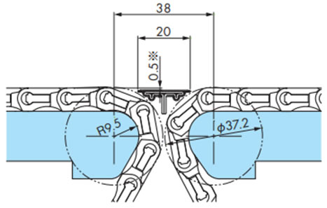
2-8-3. WT1500 series, BTN5 type in-line layout
The placement of the dead plate will vary depending on the installation space, but an example is shown in the diagram below.
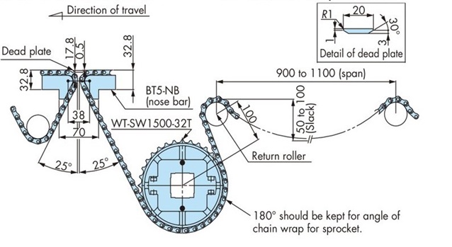
Note)
- 1. The dimensions in the diagram above are for reference only. Please make fine adjustments depending on the transfer status of the transported items.
- 2. Depending on the shape of the transported item (unstable), even a slight jerk of the chain may cause a malfunction. If this is the case, please contact us.
By using the WT1500, WT1510 series, or BTN5 type, it is possible to make straight in-line connections between conveyors.
The dead plate used at in-line can be narrowed to 20 mm.
Note)
- 1. *The parts marked with an asterisk (*) require adjustment depending on the transported items.
- 2. Compatible chains are WT1500, WT1510 series and BTN5 type only. WT1505G is not compatible.
・WT1500, WT1510 series nose bar in-line layout
・WT1515VG-W type in-line layout

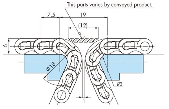
2-9. BTC4-M type in-line joint layout
- In the case of a straight line transfer with a 10T tooth sprocket
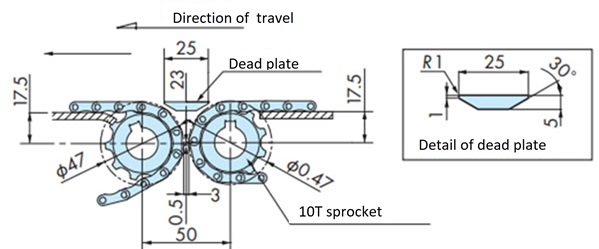
・In the case of a straight line transfer with a Φ18 shaft
Note) Adjust the dead plate level slightly depending on the transfer status of the transported items.
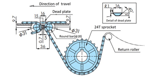
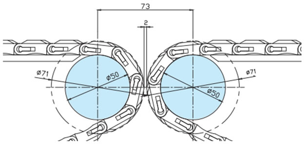
2-10. WT2520 series in-line layout
By installing a Φ50 round bar at the end of the conveyor, it is possible to reduce the transfer space between conveyors. This is a layout with forward/reverse bottom drive.
・WT2525-K type/WT2525-M type in-line layout
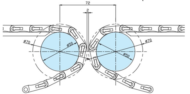
・WT2525VG-K type/WT2525VG-M type in-line layout
2-11. Orthogonal transport layout
By using our nose bars and GTO/TOD type chains, it is possible to smoothly change the angle of conveyed goods by 90 degrees without using dead plates, which are normally required.

・The installation dimensions for each chain are shown below.
Insertion transport (WT1505TOD/WT1500)
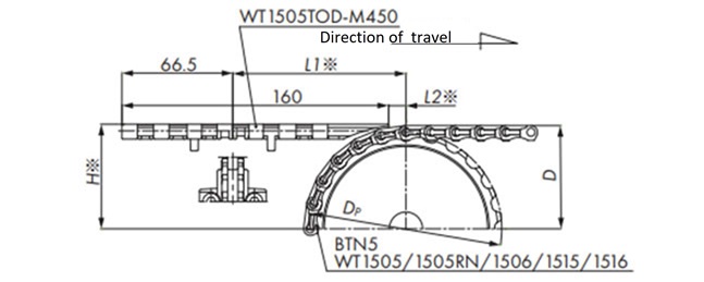
| Number of teeth | Dimensions in mm | ||||
|---|---|---|---|---|---|
| Dp | D | H ※ | L1 * | L2 * | |
| 24 | 114.9 | 61.4 | 62.2 | 103.9 | 10.4 |
| 32 | 153.0 | 80.5 | 81.3 | 104.9 | 11.4 |
| 33 | 157.8 | 82.9 | 83.7 | 105.0 | 11.5 |
Note) *The parts marked with an asterisk (*) may require adjustment depending on the transported items.
Insertion transport (WT2505TOD/WT2500)
・WT2505TOD-M450
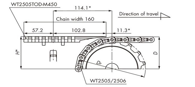
| Number of teeth | Dimensions in mm | ||
|---|---|---|---|
| Dp | D | H ※ | |
| 16 | 130.2 | 71.4 | 72.1 |
| 18 | 146.3 | 79.5 | 80.3 |
| 21 | 170.4 | 91.6 | 92.5 |
| 31 | 251.1 | 131.8 | 132.6 |
Note) *The parts marked with an asterisk (*) may require adjustment depending on the transported items.
・WT2505TOD-M750
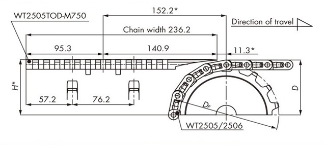
| Number of teeth | Dimensions in mm | ||
|---|---|---|---|
| Dp | D | H ※ | |
| 16 | 130.2 | 71.4 | 72.1 |
| 18 | 146.3 | 79.5 | 80.3 |
| 21 | 170.4 | 91.6 | 92.5 |
| 31 | 251.1 | 131.8 | 132.6 |
Note) *The parts marked with an asterisk (*) may require adjustment depending on the transported items.
Discharge conveyance (WT1505GTO/WT1505GTORN/WT1500)

Note) *The parts marked with an asterisk (*) may require adjustment depending on the transported items.
2-12. Orthogonal transport of WT1500 and WT1505G
Insertion transport (WT1500/WT1505G/WT1515G)
Note) *The parts marked with an asterisk (*) may require adjustment depending on the transported items.
Discharge transport (WT1500/WT1505G/WT1515G)
Note) *The parts marked with an asterisk (*) may require adjustment depending on the transported items.
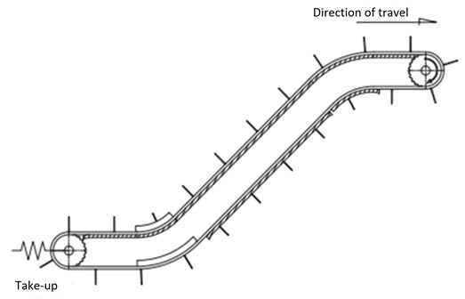
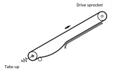
2-13. Inclined conveyor take-up
On inclined conveyors, the chain's own weight can cause it to come off the driven sprocket, so we recommend installing a take-up.
Take-up for inclined transport (horizontal + inclined + horizontal)
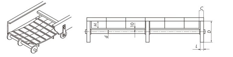
2-14. return-way of flight type chain
Roller support example
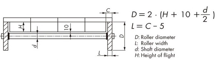
To accommodate chain slack, the number of return roller supports must be increased depending on the chain width.
Note: Additional machining of the flights is required to avoid interference with the flight parts.
Reference diagram
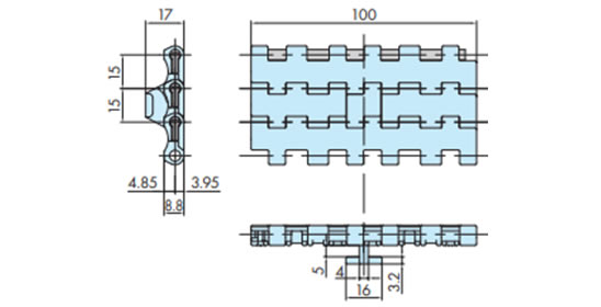
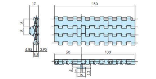
2-15. Special organization of float-preventive tabs
For the WT1515T-FW type, the configuration of float-preventive tabs differs when the chain width is 100 mm or 150 mm.
Chain width 100mm
Chain width 150mm
2-16. Transfer plate installation
The preferred placement of the transfer plate is shown below.

| Chain type | Transfer plate model number | B mm | D mm |
|---|---|---|---|
| WT1907-K | WT-TP1907-L114 | 70 | Dp2 + 9.9 |
| WT-TP1907-L190 | 100 | ||
| WT3827-K | WT-TP3827-L152 | 82 | Dp2 + 12.7 |
| WT5707-K | WT-TP5707-L220 | 82 | Dp2 + 15.5 |
Dp: Pitch circle diameter
Install the caps and mounting screws that come with the transfer plate as shown in the diagram on the right.
Also, take into consideration the thermal expansion of the chain when installing the transfer plate, and install the mounting screws as shown in the diagram below according to the operating temperature conditions.
- 1) At room temperature (20°C) with no temperature change
Install the transfer plate mounting screws 2 and 3 in the center of the oblong holes.
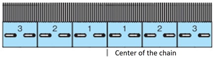
- 2) Low temperature
Install the transfer plate mounting screws 2 and 3 closer to the center of the chain.
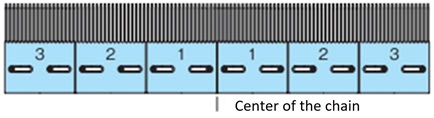
- 3) In case of high temperature
Install the transfer plate mounting screws 2 and 3 closer to the end of the chain.