technical data Top chain Selection
This page is a common page for Top chain and Plastic block chain products.
This page introduces the following items:
(Click on each item to scroll to the main text.)
- 2-1. Installing the driving and driven side wearstrip
- 2-2. Installing wearstrip (Plastic rail) on the straight section of the conveyor side
- 2-3. Installation of wearstrip on the curved section of the conveying side
- 2-4. Layout of the straight section on return-way
- 2-5. Layout of return-way curve
- 2-6. Curved section using corner discs on TPUSR chains
- 2-7. TPUN-LH type conveyor design
- 2-8. TPUH-BO type horizontal conveyor design
- 2-9. Plastic Crescent Chain Conveyor Chain
- 2-10. Conveyor extension
- 2-11. Important points to note when using heat-resistant, high-speed (KV) Top chain
Conveyor design materials
The rail layout will vary depending on the installation space, but an example is shown in the diagram below. For return-way layout, please refer to section 2-4 below.
Note: Please also refer to Plastic modular chain (mold-to-width) conveyor design document.
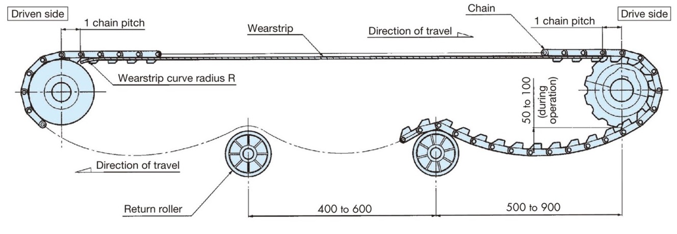
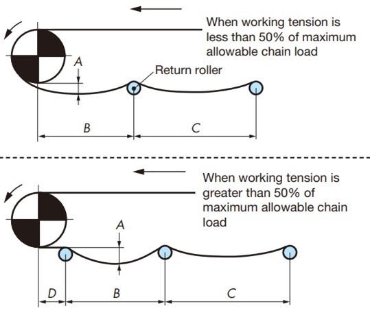
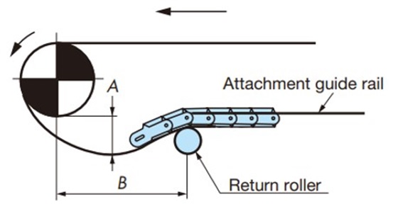
- 1) Chain slack
The intervals between the return rollers that receive return-way chain should be 500 to 900 mm, with 50 to 100 mm of slack in the chain between the return rollers. This slack prevents tooth skipping. If the interval or amount of slack is outside this range, tooth skipping may occur. - 2) Meshing angle
The "engagement angle" between the drive sprocket and chain should be 150° or more. - 3) wearstrip end
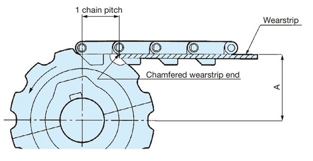
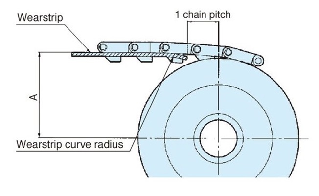
The distance from the drive and driven side wearstrip ends to the respective shaft centers should be within one chain pitch. The driven side wearstrip end should be bent or chamfered to prevent the chain from getting caught on wearstrip.
2-1. Installing the driving and driven side wearstrip
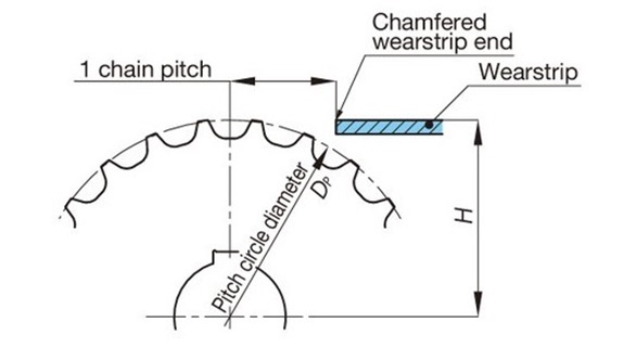
2-1-1. Sprocket and wearstrip positions
[Drive side]
Plastic modular chain (mold-to-width)
[Driven side]
For chains with top plates
Idler wheel (no teeth)
Plastic top chain
Stainless steel Top chain
Plastic block chain
Plastic Universal Chain
plastic
Modular chain (mold-to-width)
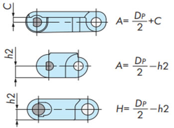
Note)
- 1. DP: Pitch circle diameter
- 2. For the idler wheel, use the pitch diameter of a sprocket with the equivalent number of teeth.
2-2. Installing wearstrip (Plastic rail) on the straight section of the conveyor side
2-2-1. carry-way
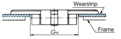
- 1. The guide width Gw should be approximately 2 mm wider than the hinge width of the chain body (Fig. 1). (For guide width Gw, see 2-2-4.)
- 2. On multiple strand line, if the chains travel in opposite directions or at different speeds even if they are the same, use a T-shaped rail or similar to prevent the top plates of the chains from coming into contact (Figure 2).
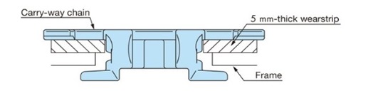
- 3. In multiple strand line, if the direction of travel and speed are the same, we recommend a chain top plate spacing of 1.4 to 3 mm (Figure 3).
- 4. We recommend using wearstrip to prevent wear on the frame itself.
- 5. The thickness of wearstrip must be at least 3 mm to prevent wear.
Figure 1. Chain carry-way
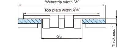
Figure 2. When multiple strand are moving in opposite directions or at different speeds
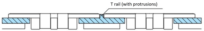
Figure 3. multiple strand with the same speed

2-2-2. wearstrip when using chain with anti-floating attachment
2-2-3. Installing the straight wearstrip
-PR type rails, PH type rails, flat rails
To take into account expansion due to heat, secure the unit to the frame with a screw at one end, leaving a gap at the joint.
(PH type rail clearance: 3 to 5 mm)
Note)
- 1. Linear expansion coefficient
Plastic rail (P-rail), PLF rail: 20 x 10-5 /℃
M rail: 9× 10⁻⁵ /℃ - 2. Plastic rail operating temperature range
Plastic rail (P-rail), PLF rail: -20 to 60°C
M rail: -20 to 80°C - 3. Do not use wearstrip in conditions where steam is present.
- 4. For heat-resistant, high-speed (KV) wearstrip, please refer to section 2-11 below.
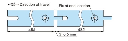
- Long straight type (Z-shaped, T-shaped, L-shaped, flat, etc. extruded wearstrip)
[When the conveyor conveyor length is long]
If you are installing long, straight wearstrip in 1m increments, please process the gaps between wearstrip as shown in the diagram below to prevent the chain from dropping.
(Gap for long, straight types: Approximately 10 mm per meter)
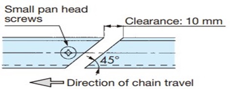
Note: For lengths of 1m or more, calculate the gap dimensions from the linear expansion coefficient.
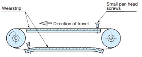
[When the conveyor conveyor length is short]
If both ends of wearstrip are fixed with flat head screws in several places, the difference in linear expansion coefficient between the running rail and the frame (made of metal) will cause wearstrip to become wavy, so please fasten the flat head screw in one place at each end.
2-2-4. Clearance between chain and wearstrip (straight section)
[Plastic top chain /stainless Top chain]
[Plastic block chain]
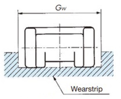
Table 9. Plastic top chain and Stainless Steel Top chain
| Model | Guide Width Gw mm |
|---|---|
| TTP, TTPH, TPF, TPS, TP-OTD, TPH, TPM, TPM-SN, TT | 44 |
| TTPDH, TTPDH-LBP | 140 |
| TN | 38 |
| TPRF2040, TP-1843G | 23 |
| TPRF2060, TS, TTUPM-P, TTUPM-PC | 32.5 |
| TTPT, TSA | 44.5 |
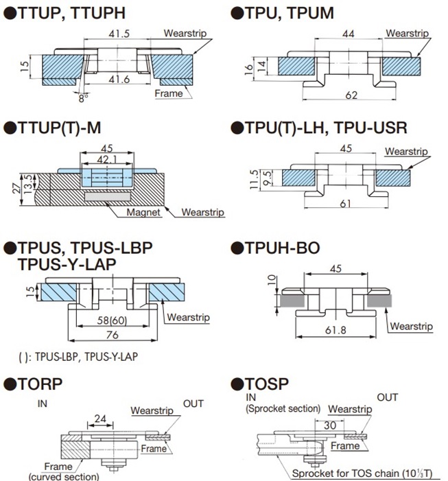
| TTUP, TTUPH, TTU, TTUPS-H | 43 |
| TPU, TPUM | 44 |
| TPU-USR | 46 |
| TPUS | 58 |
| TPUS-LBP, TPUS-Y-LAP | 60 |
| TPUSR, TP-PTS | 37 |
| TNU | 38 |
| TRU, TTUP-LLPC | 44.5 |
| TTUP(T)-M, TPU(T)-LH, TPUH-BO, TTKU, TO, TU, TTUPM838H | 45 |
| TTPM | 32 |
| TPSS | 62 |
| TTUPS | 61.5 |
| TP-36AK | 31 |
| TP-PT, TP-1873T, TP-UB36 | 34 |
| TP-1873G | 35 |
| TP-30UTW-LAP | 50.5 |
| TP-36UTW-LAP | 62 |
| TOSP | 27 |
| TORP | 48 |
Table 10. Plastic block chain /Pla Universal Chain
| Model | Guide Width Gw mm |
|---|---|
| TPUN, TPUN-LH, TP-50UNS, TP-50UNS-D76 Note)1 | 58 |
| TP-50UN-T95 | 53 |
| RSP35 | 16 |
| RSP40, RSP40-SL300 | 23 |
| RSP50 | 25.5 |
| RSP40-T-CU | 34 |
| RSP60, RSP60-CU | 33 |
| RSP60-2 | 63 |
| RSP60-CU-2 | 66 |
| RSP80 | 43 |
| RSP50-SL350 Note)2 | 26 |
Note)
- 1. We recommend a rail height of approximately 15 to 22 mm for the TPUN and TPUN-LH types.
- 2. When receiving on the top plate surface, the guide width Gw is 24.
- 3. The same model plastic pin type has the same guide width Gw as the stainless steel pin type.
2-3. Installation of wearstrip on the curved section of the conveying side
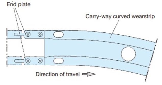
2-3-1. Installation of curved wearstrip
・Treatment of the entrance
An end plate is attached to the straight wearstrip just before the entrance of the curved Plastic rail.
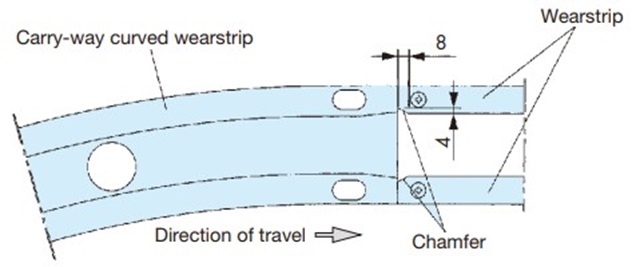
・Exit processing
Please chamfer the straight wearstrip immediately after the exit of the curved Plastic rail to prevent the chain from getting caught. (Please process wearstrip.)
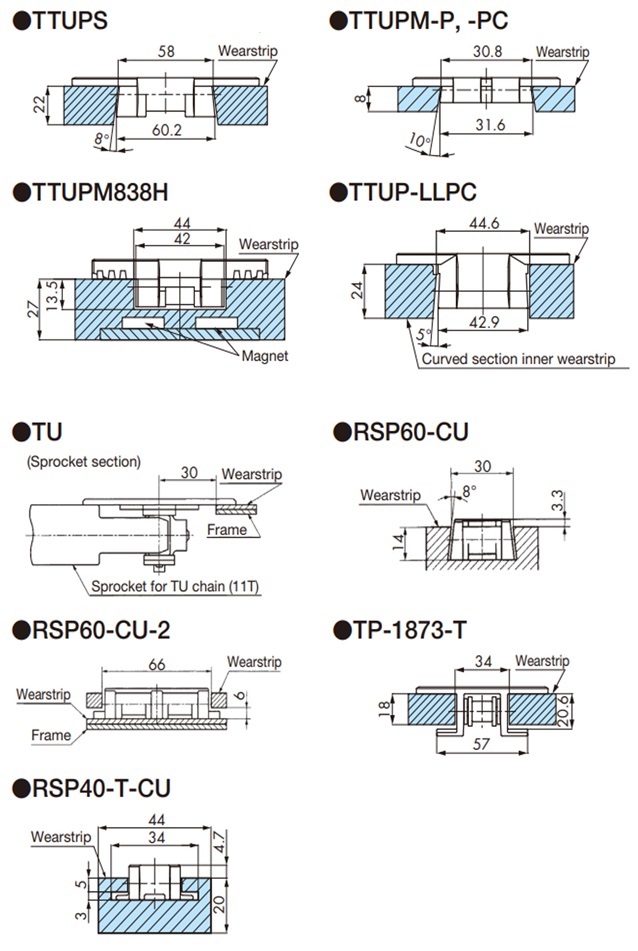
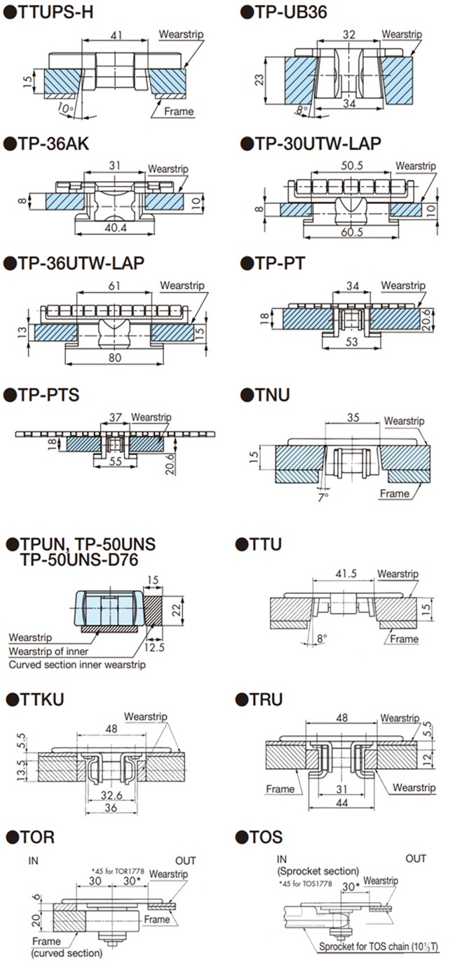
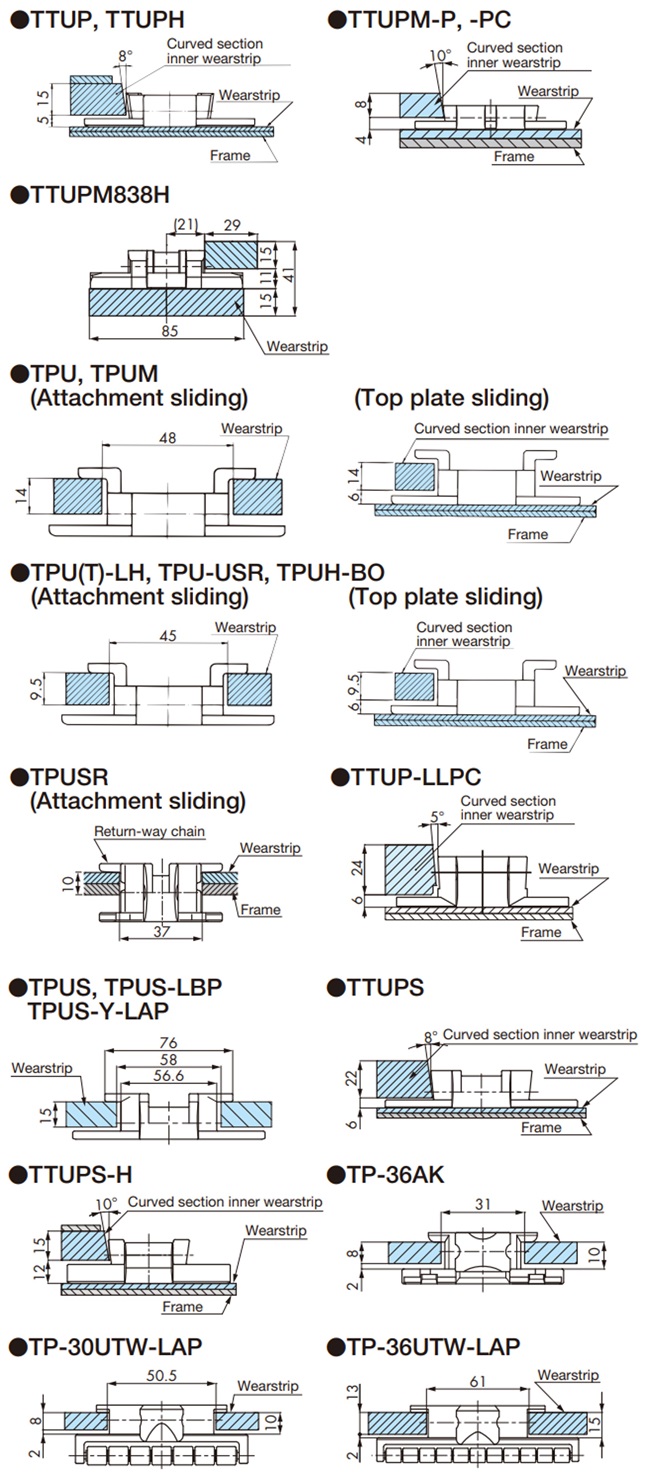
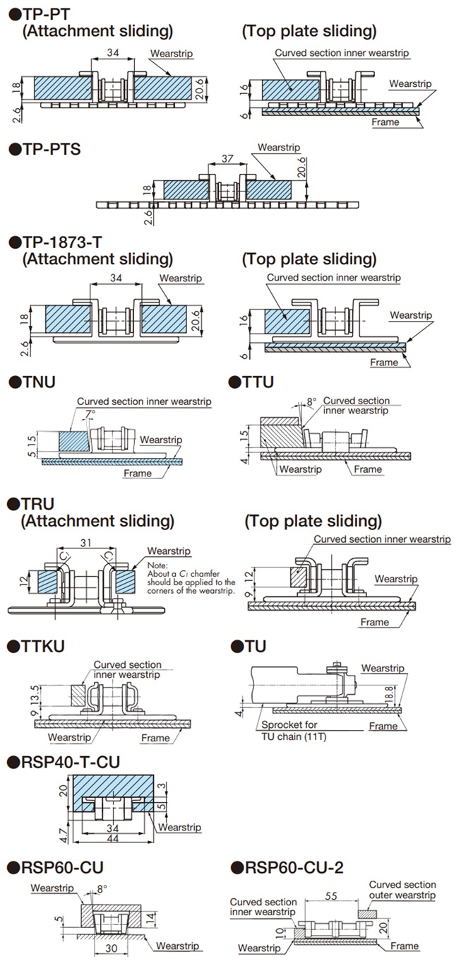
2-3-2. Cross section of each chain and wearstrip
The sprocket part is the same as the TOS type.
Note: Please refer to here.
Note: Please refer to here.
Note)
- 1. We recommend using a corner disc for TPUSR, TPUN555, TPUN550-LH, TPUN535-LH, TP-UB36, TP-50UNS, and TP-50UNS-D76.
- 2. For TTUP(T)-M and TTUPM838H types, please use the dedicated curved plastic Plastic rail with magnets.
Please contact us regarding curved plastic Plastic rail with magnets.
2-4. Layout of the straight section on return-way
The layout on return-way will vary depending on the type of chain, type and format of the conveyed material, route, etc., but a typical layout is shown below.
|
Return roller receiving methodThis is the most common and recommended layout.
|
|
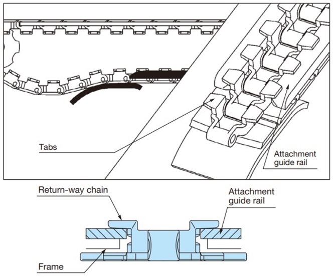
float-preventive tabs sliding methodBy using float-preventive tabs sliding on the top surface of the top plate can be eliminated. It is particularly suitable for transport conditions where scratches on the top surface of the top plate must be avoided.
|
|
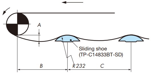
Supported by wearstripIf only a specific part of the top plate is subjected to the impact, uneven wear may occur. wearstrip should be installed in a figure eight or wave shape so that it contacts the entire top plate, and the structure should allow foreign objects to fall off easily.
|
|
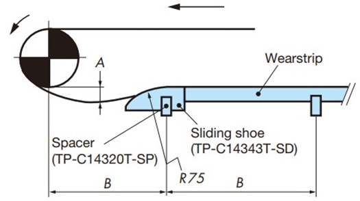
Sliding shoe support systemSuitable for relatively slow speed conveying conditions (50m/min or less). Generally suitable for accumulation chains (TTPDH-LBP) and Plastic Roller tables (ST, RT).
|
|
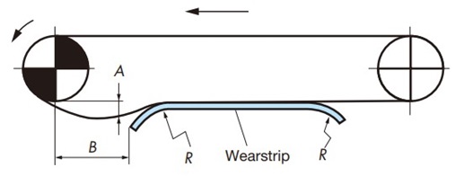
Rail-only systemAlthough this is a rational layout, it does have the disadvantage that the sliding movement can scratch the top surface of the top plate. Suitable for chains with a relatively large back bend radius.
|
|
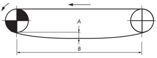
No support on return-wayThe tension due to the approximate mass of return-way chain can cause vibrations, which can make conveyance uneven. If this method is unavoidable due to a short conveyor conveyor length (1.5m or less), install a take-up mechanism on the driven side, or cut and connect and splice the chain when it stretches, and ensure that the meshing angle of the chain with the sprocket is 150° or more.
|
2-4-1.Return return-way layout details
- Received by return roller
- - The return roller is an item that supports the top surface of the chain on return-way.
- - When using return rollers, take into consideration the chain backbend radius in Table 11. We generally recommend that the chain backbend radius be equal to or less than the return roller radius, but if the backbend radius is up to about R300, it is possible to use it by keeping the chain slack small. However, it is not suitable for Plastic Roller tables or accumulation chains.
- - To improve the rotational performance of the return roller, especially when using Plastic top chain, we recommend that the inner diameter:outer diameter ratio of the return roller be 1:4 or greater. Furthermore, the use of a soft material on the outer periphery of the return roller is effective in improving rotational performance with the TP-IR18, TP-IR60 (for dry conditions only), TP-C121963RNT-RR, TP-C121966RNT-RR, TP-C121967RNFT-RR, TP-C121970RNFT-RR, TP-RR61544-RB, TP-RR62032-RB, TP-RR62044-RB, TP-RR30850, and TP-RR41050 (for both dry and wet conditions).
Note: Use high rotation return rollers at chain speeds of 50 m/min or less.

-float-preventive tabs sliding method (especially when you want to avoid scratches on the top surface of the slats)
- Supported by wearstrip
Consider wear on the chain conveying surface and arrange wearstrip so that they contact evenly across the width of the chain. Avoid using a solid support and create a structure that allows foreign objects to fall off easily.
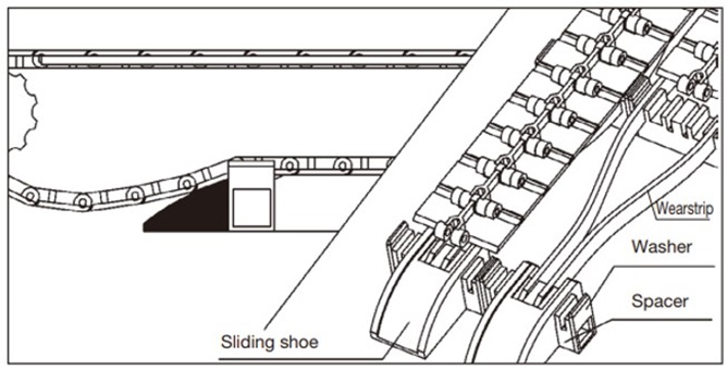
- Sliding shoe support system
Fix a Φ20 polished steel bar to the frame and attach the sliding shoe by snapping it onto the steel bar. At this time, use a set collar or similar to prevent the sliding shoe from swinging left and right.
The sliding shoe swings in accordance with the movement of the chain, using the steel bar as a fulcrum.
The ★ marks indicate holes for connecting sliding shoes lined up side by side on multiple strand conveyors.
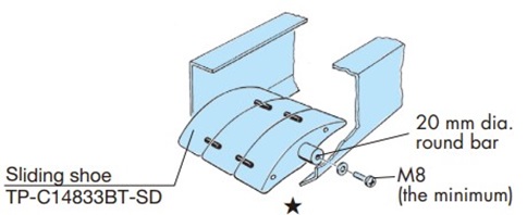
Table 11. Chain backbend radius
| Type | Chain | Backbend Radius mm |
|---|---|---|
| Plastic top /straight | TTP | 40 |
| TTPT, TTPDH | 50 | |
| TTPM | 25 | |
| TPF, TPS | 40 | |
| TP-OTD | 50 | |
| TPH, TTPH | 35 | |
| TPSS | 50 | |
| TPM(-SN) | 15 | |
| TPRF2040 | 380 | |
| TPRF2060 | 50 | |
| TN | 100 | |
| TTPDH-LBP | 400 | |
| Plastic blocks/straight and curved lines | RSP35 | 80 |
| RSP35-KV180 | 150 | |
| RSP40 | 125 | |
| RSP40-SL300 | 50 | |
| RSP40-T-CU | 25 | |
| RSP50 | 155 | |
| RSP50-SL350 | 140 | |
| RSP60, RSP80 | 180 | |
| RSP-PO8PF | 125 | |
| RSP-PO8PFT | 125 | |
| RSP60-2 | 450 | |
| RSP60-CU | 250 | |
| RSP60-CU-2 | 150 | |
| Stainless steel top/straight | TT | 180 |
| TS, TSA, TS-CTP, TSA-HTP | 330 |
| Type | Chain | Backbend Radius mm |
|---|---|---|
| Plastic top /curve | TTUP, TPU, TPU-USR, TTUPS | 40 |
| TTUPS-H | 170 | |
| TTUPH | 35 | |
| TTUP(T)-M, TPU(T)-LH, TPUH-BO, TPUS | 50 | |
| TTUPM-P | 20 | |
| TTUP-LLPC | 70 | |
| TTUPM838H | 100 | |
| TP-UB36, TTUPM-PC | 30 | |
| TPUM | 15 | |
| TPUSR826 | 25 | |
| TPUSR550 | 50 | |
| TP-36AK | 75 | |
| TNU | 100 | |
| TP-PT, PTS | 150 | |
| TP-1873T | 305 | |
| TP-1843G, 1873G | - | |
| TPUS-LBP | 400 | |
| TPUS-Y-LAP | 250 | |
| TP-30UTW-LAP | 180 | |
| TP-36UTW-LAP | 160 | |
| TPUN555, TPUN-LH | 25 | |
| TP-50UNS | 25 | |
| TP-50UNS-D76 | - | |
| TP-50UN-T95 | 500 | |
| TPCC | 35 | |
| TORP, TOSP | - | |
| Stainless steel top/curved | TTU | 100 |
| TTKU, TRU | 300 | |
| TO, TU | - |
Note)
- 1. "-" indicates a chain that (almost) never backbends.
- 2. The back vent radius of the RSP60 before the model change was 450mm.
- 3. The same type of plastic pin type has the same back bend radius as the stainless steel pin type.
2-5. Layout of the straight section on return-way
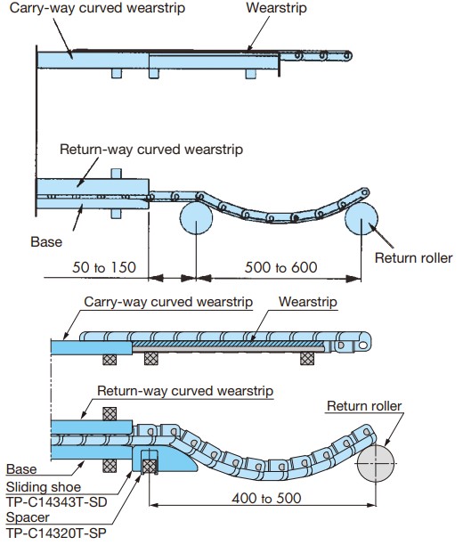
2-5-1. Installation of curved Plastic rail return-way
On both ends of return-way curved Plastic rail, install return rollers or sliding shoes (TP-C14343T-SD) 50 to 150 mm away from the base to guide the chain.
Conveyor side cross section
2-5-2. Cross section of each chain and wearstrip
Note) Please use corner discs for TPUSR, TPUN550-LH, TPUN535-LH, TP-UB36, TP-50UNS, and TP-50UNS-D76.
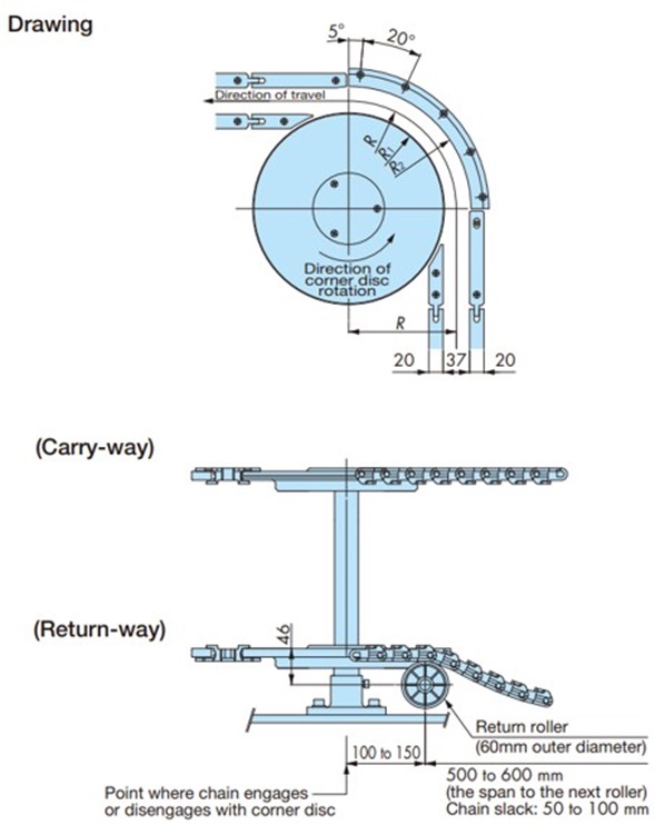
2-6. Curved section using corner discs on TPUSR chains
・TPUSR826
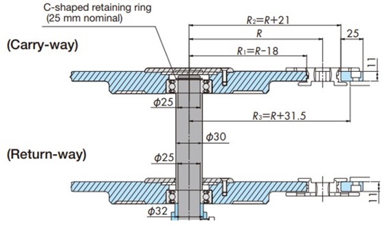
・TTPUSR550
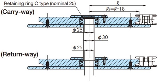
(Explanation of symbols)
- ・ R: Chain lateral bending radius (mm)
- ・ R1: Corner disc outer radius (mm)
- ・ R2: Inner radius of outer chain wearstrip (mm)
- ・ R3: Inner circumference of the conveyor frame for fixing the outer wearstrip (mm)
For conveyors that use return rollers to support return-way straight section, be sure to install return rollers at the entrance and exit of corners to provide guidance, as shown in the diagram below.
Note: Recommended for use in dry conditions.
2-7. TPUN-LH type conveyor design
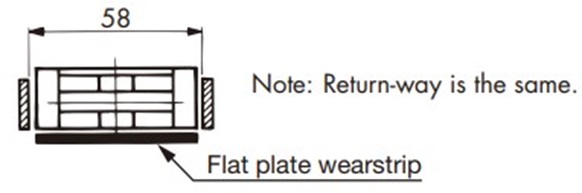
2-7-1.When using wearstrip
- Rod-shaped rail
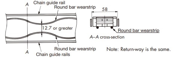
- Plate rail
2-7-2. When using corner discs
・Curve section
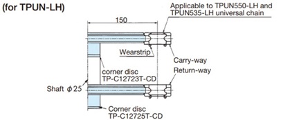
- Corner disc installation
- Curved section of vertical transport
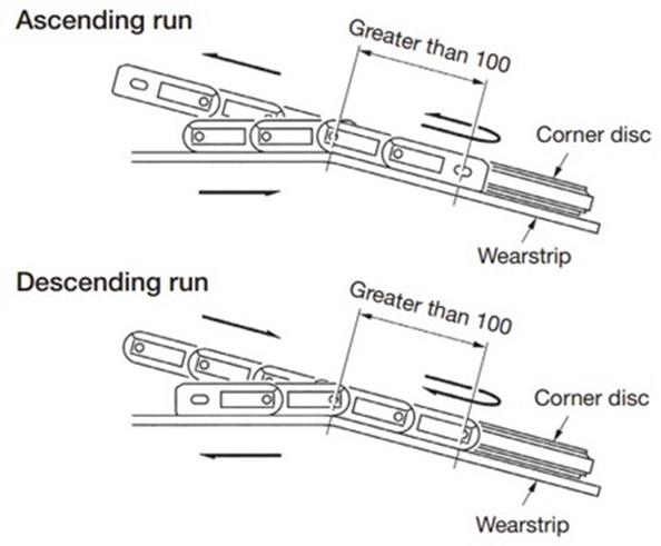
To prevent the chain from coming off the corner disc, make sure the chain and corner disc are flush as they enter and exit the corner disc.
2-8. TPUH-BO type horizontal conveyor design
2-8-1. Sprockets and corner discs during horizontal transport
Horizontal conveyance
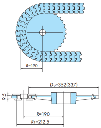
(Explanation of symbols)
- ・ DO: Outer diameter of horizontal conveying sprocket (corner disc) (mm)
- ・ R: Chain lateral bending radius (mm)
- ・ R1: Inner radius of outer chain wearstrip (mm)
Note)
- 1. For horizontal transport, install a mechanism to absorb chain elongation.
- 2. When the chain wraps around the sprocket or corner disc during horizontal transport, the chain may move up and down slightly.
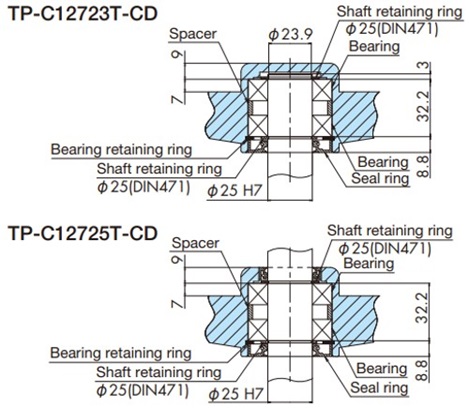
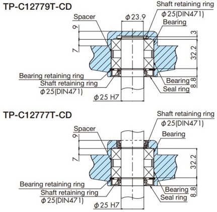
2-8-2. Installing the sprocket and corner disc shaft
- Horizontal transport sprocket installation
- 1. press fit fit the hub with keyway TP-C12773T-HB onto the horizontal transfer sprocket TP-C12781LT-SPR.
- 2. Fix the sprocket to the Φ25 shaft (with key), and finally insert the M8 screw.
- Corner disc installation
2-9. Plastic Crescent Chain Conveyor Chain
wearstrip arrangement
This may vary depending on the space available, but please refer to the example below.
*When using TO-type stainless Top chain, please refer to the example below to confirm the chain dimensions when arranging wearstrip.
・Example of wearstrip installation (1)
・When using TOSP1143 + corner sprocket
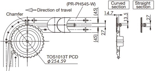
Please chamfer the entrance and straight rail immediately after the exit of the curved Plastic rail to prevent the chain from getting caught.
Note: If you are considering the PR-PH545-W, please contact us.
・Example of installation of wearstrip (2)
・When using TORP1143 + corner sprocket
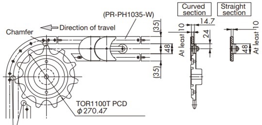
Please chamfer the entrance and straight rail immediately after the exit of the curved Plastic rail to prevent the chain from getting caught.
Note: If you are considering PR-PH1035-W, please contact us.
・Example of installation of wearstrip (3)
・When using TORP1143 + curved corner plastic Plastic rail
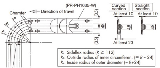
Please chamfer the entrance and straight rail immediately after the exit of the curved Plastic rail to prevent the chain from getting caught.
Note: If you are considering PR-PH1035-W, please contact us.
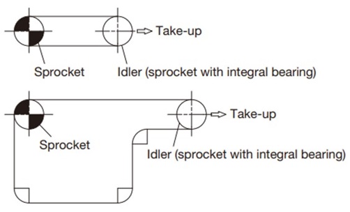
Conveyor layout considerations
Be sure to install a take-up mechanism to absorb stretching caused by wear and temperature changes on the conveyor.
Please refer to the example below.
2-10. Conveyor extension
As the conveyor conveyor length increases, the chain tension increases and the strength becomes insufficient. In such cases, the conveyor is extended.
There are three ways to extend a conveyor, but the height relationship of the conveyor is important for smooth transfer of conveyed goods.
2-10-1. Parallel transfer
This is the most preferable method of transferring materials onto two parallel adjacent conveyors using only guides.
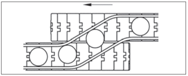
- 1. The chain height should be the same or the chain on the sending side should be slightly higher.
- 2. Guide channel should be smooth so that the transported items can be guided smoothly.
2-10-2. dead-plate (dead plate) crossing
This is a method of transferring conveyors using dead-plate (dead plate) when both conveyors are placed at right angles to each other.
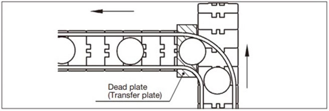
- 1. dead-plate should be slightly lower than the height of the sending chain.
- 2. The corners of dead-plate are chamfered to ensure smooth transport of goods.
- 3. Install with care to avoid contact with the chain due to the up and down movement caused by the chordal action on the driven side of the chain on the receiving side.
2-10-3. Turntable delivery
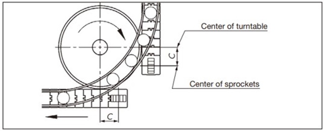
A method of actively transferring transported items using a rotating disk (turntable).
Turntable height
- - Make it slightly lower than the height of the chain on the conveying side.
- Make it slightly higher than the height of return-way chain.
Chamfer the outer periphery of the turntable.
Generally, the center of the turntable is aligned near the center of the drive and driven sprockets, but to avoid the effects of chordal action, it is better to move only the center position (C) forward, which will eliminate the effects of up and down movement and make the turntable more stable.
2-11. Important points to note when using heat-resistant, high-speed (KV) Top chain
2-11-1. When used at room temperature
- 1. We recommend that wearstrip material be steel, steel (hard chrome plated and buffed), or stainless steel (cold-rolled material).
- 2. Black Wear debris will be generated. Clean it regularly.
- 3. Perform slow starts and slow stops.
2-11-2. When using at high temperatures
- 1. We recommend using stainless steel (cold-rolled material) for wearstrip material.
- 2. When fixing wearstrip, fix only one end, taking thermal expansion into consideration. Also, take thermal expansion into consideration when determining the gap between wearstrip.
(Reference: Linear expansion coefficient of SUS304...1.8×10-5 /℃)
(Example) Fixing stainless steel wearstrip and gaps between wearstrip
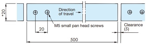
*... Applies to TTP-KV, TPS-KV, TTUP-KV, and TPU-KV. For RSP35(40/60)-KV, see Table 10 above.
Gap S when wearstrip length is 500 mm
| Operating temperature ℃ | 50 ~ 100 | 100 ~ 150 | 150 ~ 200 | 200 ~ 250 |
|---|---|---|---|---|
| Gap S | 1.5 | 2 | 2.5 | 3 |
- 3. Standard steel sprockets can be used when the ambient temperature is below 150°C.
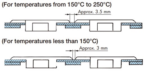
For temperatures above 150°C, a special sprocket is required. Please contact us for details. - 4. When using multiple strand chains, the gap between the chains should be the following dimensions.
- 5. Take-up is required to absorb thermal expansion of the chain. Always adjust the take-up after the chain has reached operating temperature.
When lowering the temperature, be sure to loosen the take-up first. - 6. Black Wear debris will be generated. Clean it regularly.
- 7. When starting up, use a slow start (using inverter control, etc.), and when stopping, use a slow stop.

