technical data linear actuator Power Cylinder Selection
Selection: U Series
Requirements
Machines and methods used
Thrust or load N{kgf}
Stroke mm
Speed mm/s
Frequency of use Number of starts/min
Usage time (hours/day) and annual operating days (days/year)
The nature of the load on the machine used
Usage environment
Power supply voltage, frequency
Selection Procedure
Deciding the model STEP1
Please choose the type (B or C) based on the operating environment standards and usage method.
Deciding the model number STEP 2
- (1) Calculate the annual travel distance based on the stroke, frequency of use, and duration of use.
Annual travel distance km = Actual stroke m × frequency of use times/day × number of operating days/year × 10-3
- (2) Refer to Table 1 to determine Service factor based on the load characteristics and the machine being used.
- (3) Multiply the thrust or load by Service factor to obtain the corrected thrust.
- (4) Based on the corrected thrust and annual travel distance, determine the frame number from the graph below "Expected travel distance", then select the applicable model number from the list of standard models (here) based on the stroke, speed, power supply voltage and frequency.
Table 1 Service factor
| Load Nature | Examples of machines used | Service factor |
|---|---|---|
| Smooth operation without shocks small inertia |
Damper and valve opening and closing Conveyor switching device |
1.0~1.3 |
| Operation with light shock During inertia |
Opening and closing hopper gates, various transfer devices, lifting and lowering of various lifters | 1.3~1.5 |
| Operation with large shocks and vibrations Large inertia |
Heavy-duty transport by cart, buffer for belt conveyor, reversing opening and closing device for large lid | 1.5~3.0 |
Note: The above Service factor are general guidelines and should be determined taking into consideration the conditions of use.
Checking the characteristics STEP 3
- (1) Use the product at or below the allowable frequency (Table 2).
- (2) Check Percentage duty cycle.
- (3) Check the coasting distance and stopping accuracy in Table 3 below.
Table 2 Permissible frequency of use
| Series name and type | LPUB・LPUC | |||||||
|---|---|---|---|---|---|---|---|---|
| Motor capacity (kW) | 0.75 | 1.5 | 2.2 | 3.7 | 5.5 | 7.5 | 11 | 15 |
| Thrust/speed | 6000S | 6000L | 6000M | 6000H | ||||
| 8000S | 8000L | 8000M | 8000H | |||||
| 12000L | 12000M | 12000H | ||||||
| 16000L | 16000M | 16000H | ||||||
| 22000L | 22000M | 22000H | ||||||
| 32000L | 32000M | 32000H | ||||||
| 50000L | 50000M | 50000H | ||||||
| Number of starts (times/min) | 4 | 4 | 4 | 4 | 3 | 3 | 2 | 2 |
| Percentage duty cycle (%ED) | 25%ED | |||||||
Note: This usage frequency is determined by the heat generated by the motor. It does not take into account the lifespan of the cylinder body.
The allowable operating frequency of Power Cylinder U Series is within the range that satisfies the number of starts and Percentage duty cycle shown in the table above. Percentage duty cycle is expressed by the following formula.
Percentage duty cycle (%ED) = Operation time per cycle Operation time per cycle + Down time x 100%
Table 3 Coasting distance and stopping accuracy (reference values)
| How to use | Brake internal connection | Brake external connection * | |||||||
|---|---|---|---|---|---|---|---|---|---|
| Push-up load | Suspended load | Push-up load | Suspended load | ||||||
| Model number | coasting distance | Stopping Accuracy | coasting distance | Stopping Accuracy | coasting distance | Stopping Accuracy | coasting distance | Stopping Accuracy | |
| LPUB6000
LPUC6000 |
S | 0.6 | ±0.2 | 0.8 | ±0.2 | 0.5 | ±0.1 | 0.6 | ±0.1 |
| L | 2.7 | ±0.6 | 4.4 | ±1.2 | 1.8 | ±0.4 | 3.4 | ±0.9 | |
| M | 4.5 | ±1.0 | 7.4 | ±2.0 | 2.7 | ±0.5 | 5.5 | ±1.5 | |
| H | 7.6 | ±1.7 | 12.2 | ±3.2 | 4.6 | ±0.9 | 9.0 | ±2.4 | |
| LPUB8000
LPUC8000 |
S | 1.9 | ±0.4 | 2.9 | ±0.7 | 1.3 | ±0.2 | 2.2 | ±0.5 |
| L | 3.6 | ±0.8 | 5.8 | ±1.6 | 2.2 | ±0.4 | 4.3 | ±1.1 | |
| M | 5.6 | ±1.2 | 8.4 | ±2.1 | 3.4 | ±0.7 | 6.1 | ±1.5 | |
| H | - | - | - | - | 5.4 | ±1.0 | 8.7 | ±2.0 | |
| LPUB12000
LPUC12000 |
L | 2.1 | ±0.5 | 3.0 | ±0.8 | 1.3 | ±0.2 | 2.2 | ±0.5 |
| M | 3.5 | ±0.8 | 5.1 | ±1.3 | 2.1 | ±0.4 | 3.6 | ±0.9 | |
| H | - | - | - | - | 3.6 | ±0.7 | 5.9 | ±1.4 | |
| LPUB16000
LPUC16000 |
L | 2.8 | ±0.6 | 4.0 | ±1.0 | 1.7 | ±0.3 | 2.8 | ±0.7 |
| M | - | - | - | - | 2.6 | ±0.5 | 4.0 | ±0.9 | |
| H | - | - | - | - | 3.9 | ±0.7 | 8.6 | ±2.4 | |
| LPUB22000
LPUC22000 |
L | - | - | - | - | 1.3 | ±0.3 | 2.0 | ±0.4 |
| M | - | - | - | - | 2.0 | ±0.4 | 4.2 | ±1.0 | |
| H | - | - | - | - | 2.7 | ±0.5 | 4.4 | ±1.1 | |
| LPUB32000
LPUC32000 |
L | - | - | - | - | 1.3 | ±0.3 | 2.0 | ±0.4 |
| M | - | - | - | - | 2.0 | ±0.4 | 4.2 | ±1.0 | |
| H | - | - | - | - | 2.7 | ±0.5 | 4.4 | ±1.1 | |
| LPUB50000
LPUC50000 |
L | - | - | - | - | 1.3 | ±0.3 | 2.0 | ±0.4 |
| M | - | - | - | - | 2.0 | ±0.4 | 4.2 | ±1.0 | |
| H | - | - | - | - | 2.7 | ±0.5 | 4.4 | ±1.1 | |
*Please refer here for wiring for Brake external connection.
Load Type
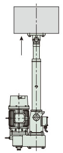
Push-up load
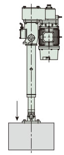
Suspended load
vertical use
Note: In actual operation, it is necessary to prevent the rod from rotating.
Coasting distance: The distance until the limit switch or stop button is activated and the machine stops. This coasting distance varies depending on the load and the number of times the switch or stop button is operated.
Stopping accuracy: The amount of variation in the stopping position when stopping is repeated.
Estimated life span
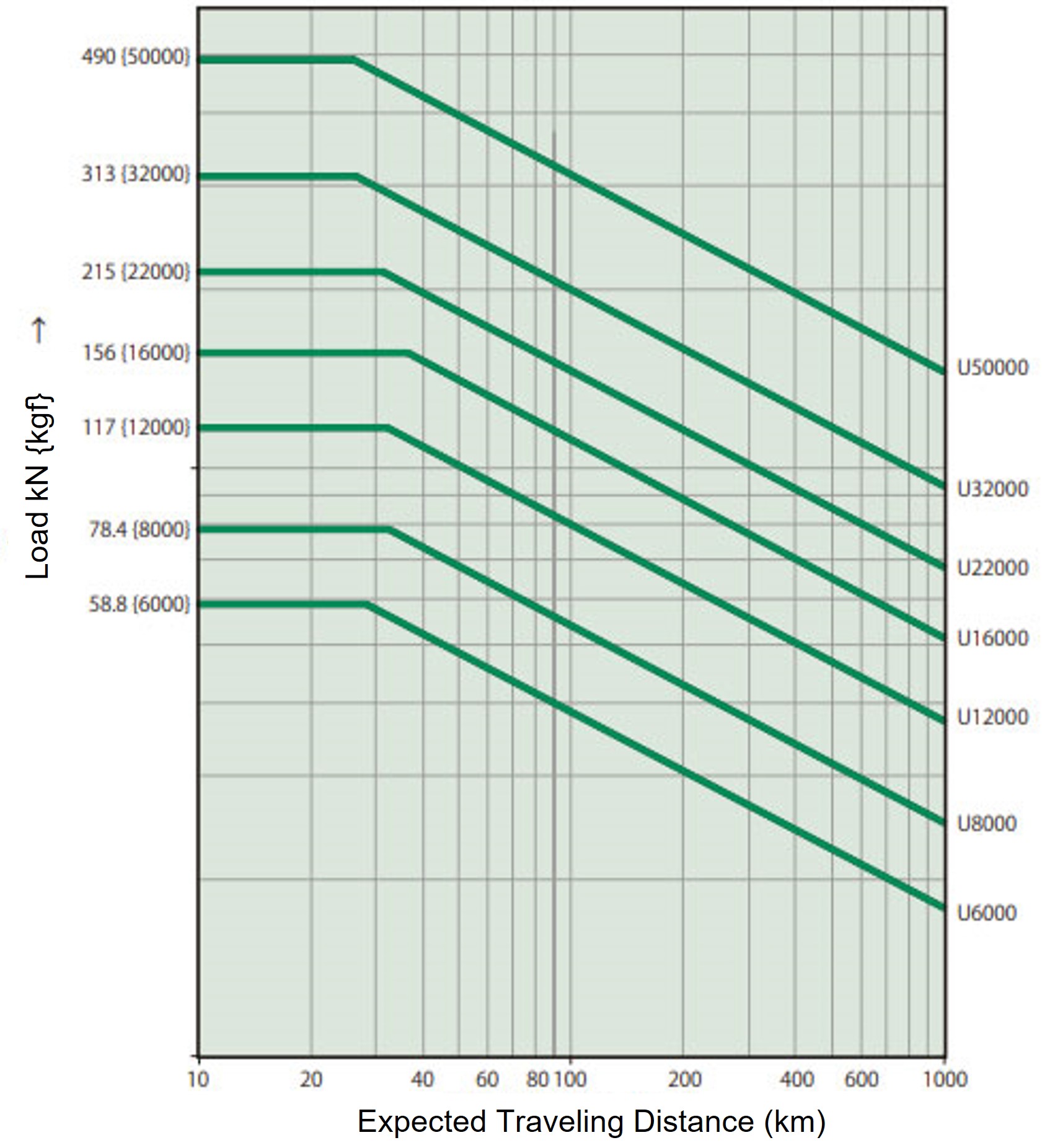
The product life of Power Cylinder U Series should be determined by travel distance of the cylinder (nut).
Cylinder (nut) travel distance
The life of Ball screw is determined by flaking caused by fatigue on the rolling surface. Please check the approximate lifespan using this expected travel distance graph.
However, if there is a lot of impact or if proper lubrication and maintenance are not performed, the expected travel distance will be significantly reduced.
Expected travel distance (km) = Actual load stroke (m) × frequency of use (times/day) × number of operating days/year × 10-3 × expected number of years
The graph on the right is based on the L10 lifespan. L10 lifespan is the lifespan that 90% or more of the total can achieve, expressed in terms of travel distance. When selecting Power Cylinder based on lifespan, please select the model number from the graph on the right.
If the load fluctuates significantly midway through the stroke, calculate the equivalent load (P M) using the formula below.
PM = PMIN + 2×PMAX 3
P M: Equivalent load N{kgf}
P MIN: Minimum load N{kgf}
P MAX: Maximum load N{kgf}
If you are looking for even greater travel distance, please consider the N specification (here).
Expected travel distance
Selection example
Usage: Hopper gate opening and closing (2 intermediate stops, forward and backward limit pressing stops)
Required thrust: 41.2kN{4200kgf}
Stroke: 1000mm
Speed: 1000mm in about 45 seconds
Frequency of use: 1 round trip per 60 minutes (1 round trip/hour)
Usage time: 8 hours/day, 250 days of operation/year. Service life: approx. 5 years.
Load characteristics: Light impact operation, forward and reverse load
Usage environment: Outdoor installation, dusty, temperature 0-35℃
Power supply: 220V 60Hz
Determining the Type
With push stop and internal stop → Select C type
Deciding the model number
- 1. Service factor: 1.3
- 2. Corrected thrust: 41.2kN{4200kgf}×1.3 = 53.6kN{5460kgf}
- 3.Model number: LPUC 6000 L10 K2 J
K2...Stop at 2 intermediate points
J......With bellows (high dust content)
Characteristics check
- 1. Number of startups
- Start times: 2 times/60min < 4 times/min
- Percentage duty cycle:
1000mm 22mm/sec* ×2 times (1 round trip) 60 minutes × 60 seconds × 100 = 2.5% < 25%*Speed calculation 1000mm / 45 seconds = 22mm / second
- 2. Total number of push (pull) stops: 2 times/reciprocation, service life 5 years (250 days/year)
- 2×1×8×250×5 = 2×10 4 times < 10×10 4 times
Checking the lifespan
- 1. Annual travel distance: 1.0 x 2 x 1 time/hour x 8 hours/day x 250 days/year x 10-3 = 4 km
- 2. Expected mileage life: 4km x 5 years = 20km
- 3. Equivalent load: P M = 53.6 + 2×53.6 3 = 53.6kN{5460kgf}
*The above load - expected travel distance satisfies the expected mileage life of LPUC6000.
Selection considerations: U series
Brake holding power
The load holding force of Power Cylinder U series when stopped is greater than the rated thrust, so it can be used to hold the rated load. This holding force is generated by the braking action of the brake-equipped motor. The brake is a spring-operated type that always applies braking force with spring force when stopped, and the brake torque has a holding force of 150% or more of the motor's rated torque.
*When selecting Power Cylinder, please select Power Cylinder with sufficient thrust, taking into account a safety factor, so that the working load (static and dynamic) does not exceed the rated thrust.
Brake stop
This method activates and stops the brake by operating a limit switch or a stop button, allowing for multi-stage positioning such as upper and lower stroke limits and intermediate stops. The coasting amount and stopping accuracy vary depending on the operating speed and load.
When precise positioning is required or when the operating speed is high, we recommend Brake external connection. When setting the limit switch, give a stop signal taking into account the coasting distance.
Reference values are shown in Table 3 above.
C-type press stop allowable number of times
When pushing (pulling) and stopping frequently
If you use it more than 10 times a day, please refer to the standard total number of stops by model in the table below.
| Type | LPUC6000~LPUC32000 | ||
|---|---|---|---|
| speed | S,L | M | H |
| Reference total number of stops (×10 4 times) | 10 | 3 | ※ |
- Note)
1. If you are using the product for a push (pull) stop, we recommend that you use a separate wiring for the brake section. - 2. If you are using the product beyond the limits in the table above, we recommend stopping the stroke by using the stroke adjustment LS.
- 3. When using with a push (pull) stop, the strength of the mating device should be 250% or more of the rated thrust.
- 4. When the cylinder stops, use the inverter to decelerate it.
*The life span is affected by the amount of deflection of the disc spring, so the more you decelerate, the more you can increase the standard total number of stops.
For example, if you use H speed, the total number of standard stops will be up to 100,000 if you stop at the same speed as S speed. Please contact us for more information. - 5. The UC50000 cannot be used for regular push (pull) stop.
Allowable weight when driving horizontally
The safety device does not work at start-up when opening and closing the damper or hopper gate, or when performing normal reversing, tilting, or lifting, but if the inertia is large, such as when the cart moves horizontally, the safety device will work at start-up and operation may not be smooth. Please refer to Table 4 for the allowable mass m for each model.
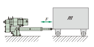
- Cart mass: m kg
- Friction coefficient: μ
- Bogie running resistance: = μ m ≦ Rated thrust
Table 4 Allowable mass m
| Power Cylinder model number | LPUB6000 LPUC6000 |
LPUB8000 LPUC8000 |
LPUB12000 LPUC12000 |
LPUB16000 LPUC16000 |
LPUB22000 LPUC22000 |
LPUB32000 LPUC32000 |
LPUB50000 LPUC50000 |
|
|---|---|---|---|---|---|---|---|---|
| speed | L | 42000 | 51000 | 170000 | 204000 | 305000 | 680000 | 960000 |
| M | 35000 | 40000 | 123000 | 160000 | 230000 | 490000 | 1080000 | |
| H | 25000 | 32000 | 74000 | 100000 | 307000 | 670000 | 720000 | |
Note: This is not a problem at low speeds (S).
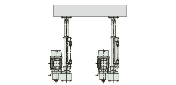
Linked operation method
Power Cylinder can be used for transporting and lifting work by sharing the load among several Power Cylinder as shown in Figure 1. This is because there is little change in speed due to load fluctuations.
Please pay attention to the items on the right when selecting.
Figure 1: Interlocking operation of several Power Cylinder
Control Method
To start, turn on the power for all units at the same time, and to stop them, use the limit switch on each Power Cylinder. Avoid controlling all units with one limit switch, as this will cause cumulative stroke errors.
Linkage Accuracy
The speed fluctuation of each Power Cylinder during operation is caused by load fluctuations and is generally about 5%. For variations when stopping, refer to the stopping accuracy in Table 3 above. If you wish to synchronize, please use the multi-specification.
Required thrust per unit N{kgf} Number of Power Cylinder used x Multiple factor
Table 5. Multiple factor
| Number of Power Cylinder used | 2 units | 3 units | 4 units | 5 units | 6 units |
|---|---|---|---|---|---|
| Multiple factor | 0.8 | 0.7 | 0.6 | 0.55 | 0.5 |

