technical data Power-Lock Selection and Procedure
If you would like to see the selection procedures and important points, please proceed below.
If you would like to narrow down or tentatively select a product series,
Please click here.
If your usage conditions have been decided and you would like a detailed selection,
Please click here.
EL Series Selection
1. Check the maximum torque and thrust load
The maximum torque and thrust load are calculated by Service factor in the transmission capacity.
*When connecting a servo motor or stepping motor, use the maximum torque (peak torque) of each as the maximum generated torque (Tmax).
| SI units |
|---|
|
Tmax = 9550 × H n ・f Tmax = Maximum torque (N・m)
|
| Gravity Units |
|---|
|
Tmax = 974 × H n ・f Tmax = Maximum torque (kgf・m)
|
Pmax = Pax・f
- Pmax: Maximum thrust load kN{kgf}
- Pax: Thrust load kN{kgf}
- f: Service factor
f: Service factor
| Load Condition | Service factor | |
|---|---|---|
| Smooth load without shock | Small inertia | 1.5~2.5 |
| Light shock load | Medium inertia | 2.0~4.0 |
| High impact loads | Large inertia | 3.0~5.0 |
When only torque is applied
Compare the Tmax obtained above with the catalog transmission torque Mt.
Mt ≧ Tmax → Can be used.
Mt < Tmax → Consider increasing the model number or using multiple units.
When torque and thrust load are applied simultaneously
The combined load M R is calculated and compared with the transmitted torque M t.
MR = Tmax2 + (Pmax × d 2 )2
- Tmax: Maximum torque N・m{kgf・m}
- Pmax: Maximum thrust load N{kgf}
- d: shaft diameter m
Compare the M R calculated above with the catalog transmission torque Mt.
M t ≧ M R → Can be used.
M t < M R → Consider increasing the model number or using multiple units.
*This series can be used with multiple units. When using multiple units, multiply Mt by the multiplier shown in the table below to determine the transmission torque.
| Number used | 1 | 2 | 3 | 4 |
|---|---|---|---|---|
| Magnification | 1 | 1.55 | 1.85 | 2 |
2. Calculation of effective pressure, transmission torque, and surface pressure
(1) When the required transmission torque value Mt differs from the transmission torque value [Mt] shown in "Model number and specifications."
Calculate the required effective pressure Fe, thrust load Pax, and surface pressure values P and P' using the following formula.
- C 1 = Mt / [Mt] (ratio of required transmission torque)
- Fe = C 1 × [Fe] N{kgf} (effective pressure)
- F = Fo + Fe N{kgf} (total applied pressure)
- Pax = C 1 × [Pax] N{kgf} (thrust load)
- P = C 1 × [P] MPa{kgf/mm 2} (shaft side pressure)
- P' = C 1 × [P'] MPa{kgf/mm 2} (Boss side pressure)
- Mt: Required transmission torque value N・m{kgf・m}
For Fo, [Fe], [Mt], [Pax], and [P'], please refer to "Model Number and Specifications."
(2) When the required effective pressure Fe differs from the effective pressure [Fe] shown in "Model Number and Specifications."
Calculate the transmission torque value Mt, thrust load Pax, and surface pressure P and P' using the following:
- C2 = Fe / [Fe] (ratio of required effective pressure)
- Mt = C 2 × [Mt] N・m{kgf・m} (transmission torque)
- Pax = C 2 × [Pax] N{kgf} (thrust load)
- P = C 2 × [P] MPa{kgf/mm 2} (shaft side pressure)
- P' = C 2 × [P'] MPa{kgf/mm 2} (Boss side pressure)
- Fe: Required effective pressure N{kgf}
For Fo, [Fe], [Mt], [Pax], and [P'], refer to "Model Numbers and Specifications." Note: 0.25 ≦ C 2 ≦ 2
(3) When multiple Power-Lock EL units are arranged in series.
Calculate the transmission torque Mtz, thrust load Paxz, and surface pressure Pz and P'z using the following formula (z: number of Power-Lock EL No. of strands).
- Mtz = S・Mt1
- Paxz = S・Pax1
- Pz = P 1 (shaft side)
- P'z = P' 1 (boss side)
Mt 1, Pax 1, and P' 1 are values when No. of strands is one set.
| Z | S |
|---|---|
| 1 | 1 |
| 2 | 1.55 |
| 3 | 1.85 |
| 4 | 2 |
3. Consideration of the axis and boss
Power-Lock EL itself does not have a centering function. Centering should be performed using the centering guide between the shaft and hub.
The length of the centering guide should be d/2 or more, but the tolerance of the centering guide should be determined according to the required accuracy.
(1) Consideration of material strength
The boss and shaft should be made of a material with a strength that satisfies the following formula.
σ0.2S≧ 1.4 × P σ0.2B≧ 1.4 × P'
- σ 0.2S, σ 0.2B: Yield point of shaft and boss material MPa{kgf/mm 2}
- P, P': Surface pressure acting on the shaft and hub bore MPa {kgf/mm 2}
Please refer to the steel material strength table, which shows the yield point values of representative steel materials.
(2) Consider required hub outer diameter D N and the allowable hollow shaft hole diameter d B
The boss you use must have an outer diameter of at least D N, calculated using the following formula. Also, if you use a hollow shaft, use one with a hole diameter of no more than dB, calculated using the following formula.
(a) When installing the bolt on the boss side
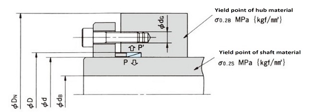
DN ≧ D σ0.2B + 0.8 × P' σ0.2B - 0.8 × P' + dG
dB ≦ d σ0.2S - 1.2 × P σ0.2S
(b) When installing the bolt on the shaft side
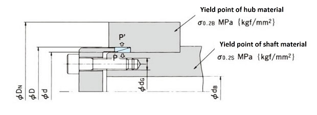
DN ≧ D σ0.2B + 0.6 × P' σ0.2B - 0.6 × P'
dB ≦ d σ0.2S - 1.6 × P σ0.2S - dG
P, P': Surface pressure on shaft side and boss side MPa {kgf/mm 2}
4. Selection of fastening bolts
(1) Bolt strength class and mechanical properties
Please refer to here for bolt strength classes and mechanical properties. We recommend using class 10.9 and 12.9 bolts whenever possible.
It is resistant to loosening due to external vibrations. It can be used with a Class 12.9 bolt and a Class 10.9 tightening torque.
(2) Examination of seat pressure
When using Class 10.9 or 12.9 bolts, please consider the surface pressure of the bolt bearing surface.
If the bearing surface pressure exceeds the limit pressure shown in the following table, the bearing surface will collapse over time, causing the bolt to lose axial force and become loose.
If the bearing surface pressure exceeds the limit, increase the mechanical strength of the pressure flange (by changing the material or applying heat treatment) or reduce the tightening force of the bolts to reduce the collapse of the bearing surface. The bearing surface area and bearing surface pressure can be calculated using the following formulas.
Bearing area = As = π 4 (D 2- da 2 max) mm 2
- D: Bolt head diameter (see data) mm
- da max: diameter of circle after neck R (see data) mm
- Bearing pressure Ps = Fv / As MPa{kgf/mm 2}
- FV: Tightening force N{kgf}
Junker limit for various materials
| material | mechanical properties | Limit surface pressure Pw MPa{kgf/mm 2} |
||||||
|---|---|---|---|---|---|---|---|---|
| Name | Germany standard |
equivalent JIS |
Tensile strength MPa{kgf/mm 2} |
Compression yield point MPa{kgf/mm 2} |
||||
| low carbon steel | St37 | S10C | 346 | 35.3 | 272 | 27.9 | 294 | 30 |
| Medium carbon steel | St50 | S30C | 505 | 51.5 | 329 | 33.6 | 490 | 50 |
| heat-treated carbon steel | C45 | S45C (Refining) |
721 | 73.6 | 478 | 48.8 | 882 | 90 |
| cast iron | GG22 | - | 228 | 23.3 | 443 | 45.2 | 980 | 100 |
5. Design of pressure mechanism
Since pressure flanges are subjected to large stresses when the bolts are tightened, please use materials with sufficient strength to prevent plastic deformation and design with ample leeway.
Please refer to the design calculation formula for the pressure mechanism recommended by our company below.
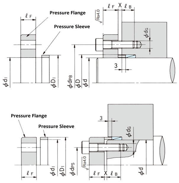
Please refer to the table below for the d 1, D 1 and X dimensions.
Model number d XD mm |
gap X Power-Lock EL No. of strands |
Pressure sleeve Pressure flange dimensions |
||||
|---|---|---|---|---|---|---|
| 1 | 2 | 3 | 4 | d1 | D1 | |
| PL010X013E | 2 | 2 | 3 | 3 | 10.1 | 12.9 |
| PL011X014E | 2 | 2 | 3 | 3 | 11.1 | 13.9 |
| PL012X015E | 2 | 2 | 3 | 3 | 12.1 | 14.9 |
| PL013X016E | 2 | 2 | 3 | 3 | 13.1 | 15.9 |
| PL014X018E | 3 | 3 | 4 | 5 | 14.1 | 17.9 |
| PL015X019E | 3 | 3 | 4 | 5 | 15.1 | 18.9 |
| PL016X020E | 3 | 3 | 4 | 5 | 16.1 | 19.9 |
| PL017X021E | 3 | 3 | 4 | 5 | 17.1 | 20.9 |
| PL018X022E | 3 | 3 | 4 | 5 | 18.1 | 21.9 |
| PL019X024E | 3 | 3 | 4 | 5 | 19.2 | 23.8 |
| PL020X025E | 3 | 3 | 4 | 5 | 20.2 | 24.8 |
| PL022X026E | 3 | 3 | 4 | 5 | 22.2 | 25.8 |
| PL024X028E | 3 | 3 | 4 | 5 | 24.2 | 27.8 |
| PL025X030E | 3 | 3 | 4 | 5 | 25.2 | 29.8 |
| PL028X032E | 3 | 3 | 4 | 5 | 28.2 | 31.8 |
| PL030X035E | 3 | 3 | 4 | 5 | 30.2 | 34.8 |
| PL032X036E | 3 | 3 | 4 | 5 | 32.2 | 35.8 |
| PL035X040E | 3 | 3 | 4 | 5 | 35.2 | 39.8 |
| PL036X042E | 3 | 3 | 4 | 5 | 36.2 | 41.8 |
| PL038X044E | 3 | 3 | 4 | 5 | 38.2 | 43.8 |
| PL040X045E | 3 | 4 | 5 | 6 | 40.2 | 44.8 |
| PL042X048E | 3 | 4 | 5 | 6 | 42.2 | 47.8 |
| PL045X052E | 3 | 4 | 5 | 6 | 45.2 | 51.8 |
| PL048X055E | 3 | 4 | 5 | 6 | 48.2 | 54.8 |
| PL050X057E | 3 | 4 | 5 | 6 | 50.2 | 56.8 |
| PL055X062E | 3 | 4 | 5 | 6 | 55.2 | 61.8 |
| PL056X064E | 3 | 4 | 5 | 7 | 56.2 | 63.8 |
| PL060X068E | 3 | 4 | 5 | 7 | 60.2 | 67.8 |
| PL063X071E | 3 | 4 | 5 | 7 | 63.2 | 70.8 |
| PL065X073E | 3 | 4 | 5 | 7 | 65.2 | 72.8 |
| PL070X079E | 3 | 5 | 6 | 7 | 70.3 | 78.7 |
| PL071X080E | 3 | 5 | 6 | 7 | 71.3 | 79.7 |
| PL075X084E | 3 | 5 | 6 | 7 | 75.3 | 83.7 |
| PL080X091E | 4 | 5 | 6 | 8 | 80.3 | 90.7 |
| PL085X096E | 4 | 5 | 6 | 8 | 85.3 | 95.7 |
| PL090X101E | 4 | 5 | 6 | 8 | 90.3 | 100.7 |
| PL095X106E | 4 | 5 | 6 | 8 | 95.3 | 105.7 |
| PL100X114E | 4 | 6 | 7 | 9 | 100.3 | 113.7 |
| PL110X124E | 4 | 6 | 7 | 9 | 110.3 | 123.7 |
| PL120X134E | 4 | 6 | 7 | 9 | 120.3 | 133.7 |
| PL130X148E | 5 | 7 | 9 | 11 | 130.4 | 147.6 |
| PL140X158E | 5 | 7 | 9 | 11 | 140.4 | 157.6 |
| PL150X168E | 5 | 7 | 9 | 11 | 150.4 | 167.6 |
(1) Bolt pitch circle diameter dp B, dp S mm
- (When d = Φ10 to Φ30) dp B = D + 8 + d G dp S = d - 8 - d G
- (When d = Φ32 to Φ150) dp B = D + 10 + d G dp S = d - 10 - d G
However, when attaching the pressure flange to the boss side, the number of bolts should be half or less of the maximum number that can be attached on the circumference of dp B.
(2) Thickness of pressure flange ℓFmm
ℓF ≧ 2 × dG
(3) Strength of pressure flange (σ 0.2F)
- When tightening a bolt with a torque of Class 8.8... σ0.2F ≧ 294 MPa {30 kgf/mm 2} (equivalent to S35C)
- When tightening a bolt with a torque of Class 10.9... σ0.2F ≧ 343 MPa {35 kgf/mm 2} (equivalent to S45C)
- When tightening a bolt with a torque of Class 12.9... σ0.2F ≧ 392 MPa {40 kgf/mm 2} (equivalent to S55C)
σ0.2F: Yield point of pressure flange MPa{kgf/mm 2}
(4) Thread engagement length ℓ B mm
ℓB ≧ 1.5 × dG
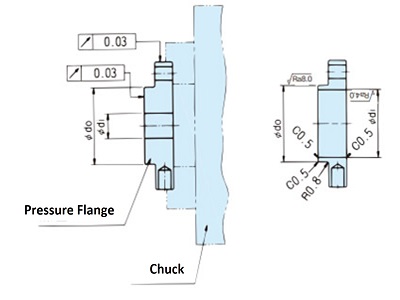
Pressure flange processing example
X: The minimum interference required when applying pressure to the ring between the pressure flange and the boss end or shaft end. The table shows the value according to the number of Power-Lock EL No. of strands.