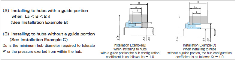
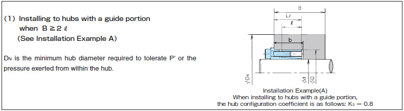
Power-Lock Simple Selection Tool
Target varieties
Power-Lock:
AS series, AS-KP series, AS-SS series
AD-N series, AD-N-KP series, AE series
RE-SS series, KE series, KE-KP series
KE-SS series, KE-LP series, TF series
TF-KP series, ML series, EF series, EL series
Use of Content
- Before using TSUBAKI Power Transmission Products Information Site Power-Lock Simple Selection Tool (hereinafter referred to as "this tool"), please be sure to read the following usage precautions and disclaimers, and use this tool only if you agree to all of the contents.
- If you do not agree, please refrain from using this tool.
Precautions for use and disclaimers
sizing Power-Lock
We will select the appropriate Power-Lock based on your specified conditions.
When selecting "Select from shaft diameter," select the model number that matches the specified shaft diameter and determine whether it satisfies the specified torque.
When selecting from torque, select the model number with the smallest shaft diameter that satisfies the specified torque.
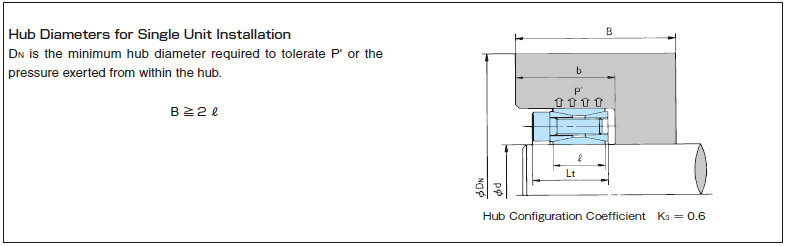
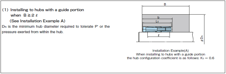
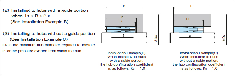
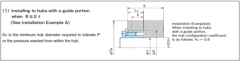
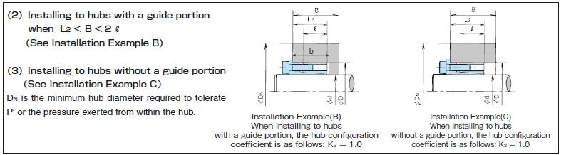
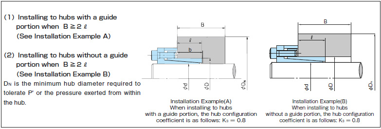
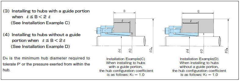
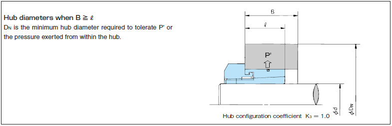
In either case, the shaft and boss surface pressure tolerance is determined, the minimum outer hub diameter required, and the maximum hollow shaft inner diameter are determined.
The radial load tolerance will be displayed, so please check it.
Enter the selection criteria
・Please use “.” for the decimal point and not “,” as the calculation error will occur.
Enter the shaft diameter
Shaft diameter: mm
Enter the transmissible torque
Transmissible Torque: N・m
Service factor:
Transmission capacity:kW
Rotational speed:r/min
If a thrust load is applied, input
Thrust load: N
If a radial load is applied, input
Radial load: N
Enter the yield point of the shaft and boss material
Shaft material yield point: MPa
Boss material yield point: MPa
Transmissible torque calculation results
N・m
*No safety factor is taken into account in the minimum required boss diameter.
For detailed selection procedures and calculation formulas, please see here.
Selection results
*For the EL series, this is the calculation result when pressure is applied using the bolt size, number of bolts, and tightening torque shown in the recommended fastening example above.
Please contact us for selection under pressure conditions other than those shown here.
| Series | Model number Click for Product Info |
Shaft diameter [mm] |
Outer diameter [mm] |
Tolerance torque [N・m] |
torque judgement |
Unit price/ delivery | series coefficient K2 |
shaft side Surface pressure [MPa] |
shaft side Surface pressure judgement |
boss Outer diameter side Surface pressure [MPa] |
boss Outer diameter side Surface pressure judgement |
need Boss material yield point |
boss strength judgement |
hollow shaft Maximum inner diameter [mm] |
|
|---|---|---|---|---|---|---|---|---|---|---|---|---|---|---|---|
| SL | Candidate 1 | ||||||||||||||
| Candidate 2 | |||||||||||||||
| Candidate 3 | |||||||||||||||