technical data Top chain Selection
If you would like to see the selection procedures and important points, please proceed below.
If you would like to narrow down or tentatively select a product series,
Please click here.
If your usage conditions have been decided and you would like a detailed selection,
Please click here.
Selection of Snap cover chain
1-1. Determining the chain size
1-1-1. Check the allowable load
Please check that the load per link is within the allowable load in Table 1.
1-1-2. Calculating the tension acting on the chain
- F = Maximum tension acting on the chain kN{kgf}
- m1 = mass of transported material (kg/m)
- m2 = Approximate chain mass (kg / m)
- S = Transfer distance (sprocket center distance) (m)
- S' = Length of the object that has slipped and accumulated (m)
- μ1 = coefficient of friction between chain and rail [conveying side] (see Table 2)
- μ2 = coefficient of friction between chain and rail [return-way] (see Table 3)
- μ3 = Coefficient of friction between the conveyed object and the chain (see Table 4)
- P = required power (kW)
- V = Chain speed (m/min)
- K = velocity factor (see Table 5)
- ηNote) = Mechanical transmission efficiency of the drive unit
- G = gravitational acceleration 9.80665m/s 2
Note: Please check the drive unit used to determine transmission mechanical efficiency.
Table 2. Coefficient of rolling friction between chain and rail (μ1)
| No lubrication | With lubrication |
|---|---|
| 0.21 | 0.14 |
Table 4. Dynamic friction coefficient (μ3) between conveyed object and chain (plastic cover)
| Material of the transported item | Resin Cover Material |
|---|---|
| Standard Series Conductive specifications |
|
| Steel cans aluminum cans |
0.25 |
| Paper pack | 0.3 |
| glass bottle | 0.22 |
| plastic containers | 0.25 |
| Industrial products (metal) | 0.25 |
Note: Without lubrication
Table 1. Snap cover chain load capacity
| Specification | Allowable load kN{kgf}/1 link | |||||
|---|---|---|---|---|---|---|
| RF06B-SC | RS40-SC | RS50-SC | RS60-SC | RS80-SC | RS100-SC | |
| Standard Series NP Series Lambda Specification |
0.03 {3} |
0.05 {5} |
0.07 {7} |
0.10 {10} |
0.15 {15} |
0.25 {25} |
| SS Series | 0.03 {3} |
0.05 {5} |
0.06 {6} |
0.09 {9} |
0.15 {15} |
0.25 {25} |
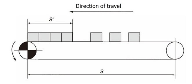
Table 3. Friction coefficient (μ2) between chain (plastic cover) and rail
| Resin Cover Material | Rail Material | |
|---|---|---|
| Stainless steel | Ultra high molecular weight polyethylene |
|
| Standard Series Conductive specifications |
0.25 | 0.25 |
Note: Without lubrication
Table 5. Velocity Factors (K)
| Chain speed m/min | velocity coefficient K |
|---|---|
| 15 or less | 1 |
| 15 ~ 30 | 1.2 |
| 30 ~ 50 | 1.4 |
| 50 ~ 60 | 1.6 |
[Calculation formula]
・SI units (kN)
F = (m1 + m2) S・μ1 + 1.1m2・S・μ2 + m1・S'・μ3 ・ G 1000
- Gravity unit (kgf)
F = (m1 + m2) S・μ1 + 1.1m2・S・μ2 + m1・S'・μ3[Check availability]
Multiply the maximum tension (F) acting on the chain by the speed factor (K) in Table 5 and check whether the following formula is satisfied.
In the case of single-line use
F × K ≦ Maximum allowable load
In the case of Nijo use
0.6F × K ≦ Maximum allowable load
1-2. Calculation of required power
・SI units (kN)
P = F・V 60 × η
- Gravity unit (kgf)
P = F・V 6120 × η

