technical data Top chain Selection
This page is a common page for our Plastic modular chain (mold-to-width), Top chain, and Plastic block chain.
If you would like to see the selection procedures and important points, please proceed below.
If you would like to narrow down or tentatively select a product series,
Please click here.
If your usage conditions have been decided and you would like a detailed selection,
Please click here.
Top chain selection procedure
Follow the steps below to select Top chain and wearstrip that best suits your conveying conditions.
(Click on each item to scroll to the main text.)
- 1. Check the transport conditions
- 2. Chain specification selection
- 3.Selection of wearstrip material
- 4. Determination of coefficients
- 5. Calculating Chain Tension and Power Requirements
- 6. Deciding on the chain format
Note: If you would like to select the low temperature and chemical resistant (UPE) specification, please fill out Plastic block chain RSP80-UPE inquiry sheet and contact us.
Step 1. Check the transport conditions
Check the transport conditions.
Transportation condition confirmation items
| 1.Transported items | (1)Material |
|---|---|
| (2) Mass per piece (g/piece) | |
| (3) Shape | |
| (4) Dimensions (length x width x height) (diameter Φ x height) mm | |
| (5) Conveying direction | |
| 2.Transportation route | (1) straight running and curved transport |
| (2) Conveyor length m | |
| (3) Conveyor width mm | |
| (4) Transport layout | |
| (5) Space m | |
| 3.Transportation conditions | (1) Transport volume BPM/pieces |
| (2) Transfer interval mm | |
| (3) Conveyor speed m/min | |
| (4) Lubrication | |
| (5) Whether or not there is stock of transported goods (whether or not there is accumulation, and the percentage) (if yes, the length of accumulation: m) | |
| 4.Usage conditions | (1) Temperature ℃ |
| (2) Corrosive conditions such as chemicals, water, and humidity (see Corrosion resistance to various liquids) (if applicable, name of liquid) | |
| (3) Presence of glass fragments, paint chips, metal powder, sand, or other abrasive materials | |
| (4) Whether or not ultraviolet light is irradiated |
2-(4) Transport layout and other notes
Step 2. Select the chain specifications
2-1. Chain specification selection
Refer to Table 1 to select the appropriate top plate material based on the material of the transported item.
Note)
- 1. Please refer to each product page for chain type, usable temperature and conditions.
- 2. For corrosion resistance, please refer to corrosion resistance against various liquids.
Table 1. Top plate material selection table
| Transported goods | Top plate Material |
Lubrication | |||
|---|---|---|---|---|---|
| None | Yes | ||||
| abrasive inclusions | |||||
| None | Yes | None | Yes | ||
| - Tin cans, aluminum cans, iron cans, metal foil containers Note 3 - Plastic, plastic-coated containers, paper containers Note 4 |
Polyacetal | C | × | A | D |
| Stainless | D | C | B | A | |
| ・Glass bottles, glass products, ceramics Note 5 ・Various industrial parts Note 6 |
Polyacetal | D | × | B | × |
| Stainless | C | C | A | A | |
Note)
- 1. "A": Highly recommended, "B": Recommended, "C": Recommended among acceptable, "D": Acceptable, "×": Inappropriate.
- 2. If antibacterial and antifungal performance is required on food and beverage conveying lines, select the antibacterial and antifungal (MWS) specification.
- 3. This includes beer cans, soft drink cans, and cans with metal lids and bottoms and fiber sides.
- 4. Includes plastic, plastic-coated and paper containers for dairy products such as milk, cheese and ice cream, confectionery, etc., as well as paper board or paper-bottom products such as soap and cereals.
- 5. Includes glass bottles and glass containers used for alcohol, food, pharmaceuticals, cosmetics, etc.
- 6. Includes machine parts, molds, castings, forgings, metal, bearings, bolts, nuts, etc.
2-2. Selecting the top plate width
Generally, the width of the top plate is selected to be slightly larger than the width of the transported item.
If the width of the conveyed item is large and there is no top plate width that is sufficient, multiple strand of chains of the same width are used. Although multiple strand strands of chains of different widths can be used, this is not recommended as the tension acting on the chain will be uneven.
You can also use Plastic modular chain.
・Top plate end face shape of cut product
The top of the cut end face is chamfered to approximately C0.5 to 0.8, and the four corners are chamfered to approximately C2.
| End shape |
|---|
 |
Note)
- 1. It is machined.
- 2. If a top plate width not listed in the catalog is manufactured, the end face shape will be as shown above.
- 3. Special end face shapes can also be processed upon consultation.
- 4. If the top plate width is small, the chamfering may differ.
- 5. Because the top plate width is machined, the main chain stamping and format will differ.
Step 3. Select wearstrip material
Select the appropriate wearstrip material from the chain specifications.
Table 2. Selection table for wearstrip materials
| Chain | wearstrip material | Lubrication | |||
|---|---|---|---|---|---|
| None | Yes | ||||
| abrasive inclusions | |||||
| None | Yes | None | Yes | ||
| Stainless steel Top chain ・For straight running ・For curved transport |
Stainless | D | D | B | B |
| steel | D | C | B | A | |
| Plastic rail (P-Rail) PLF rail |
A | × | A | × | |
| M rail SJ-CNO |
A | × | × | × | |
| Plastic top chain Plastic block chain Plastic modular chain (mold-to-width) ・For straight running ・For curved transport |
Stainless | B | D | A | A |
| steel | A | C | D | D | |
| Plastic rail (P-Rail) | D | × | A | × | |
| PLF rail | B | × | A | × | |
| M rail SJ-CNO |
A | × | × | × | |
Note)
- 1. "A": Highly recommended, "B": Recommended, "C": Recommended among acceptable, "D": Acceptable, "×": Inappropriate.
- 2. Use the Lambda type stainless Top chain without lubrication.
- 3. For heat-resistant/high-speed (KV) specifications, use stainless steel or steel wearstrip at room temperature, and stainless steel at high temperatures (over 50°C).
- 4. Recommended metal wearstrip = cold rolled material.
- 5. Steel rails are shown for oil lubrication.
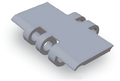
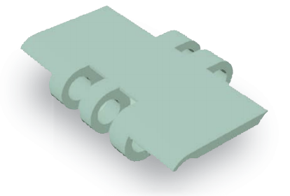
Plastic rail materials, exterior colors, and features
| Material and exterior color | Features | |
|---|---|---|
| Plastic rail (P rail) |
Ultra-high molecular weight polyethylene (Appearance color: white or green) |
・The most common rail ・Machined or extruded products ・Plastic Top chain are recommended for use in wet conditions. - It has low water absorption and is also highly resistant to chemicals and impacts. |
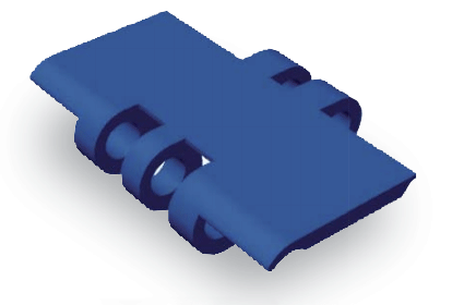
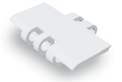
| PLF rail | Low Friction / Wear resistant Ultra-high molecular weight polyethylene (Exterior color: white) |
・Rails with lower friction and more wear resistance than P rails ・Machined or extruded products |
| M rail SJ-CNO |
Special Polyamide (M rail: exterior color: blue) (SJ-CNO: Appearance color: Purple) |
・Rails for dry conditions - Wear-resistant rails ・Machined products |
Note: Operating temperature range
Plastic rail (P-rail), PLF rail: -20℃ to 60℃
M Rail SJ-CNO: -20℃ to 80℃
Step 4. Determine the coefficients
The coefficients in Tables 3 to 6 are based on our own experimental data.
Differences may occur depending on the operating conditions, the atmosphere, the shape and material (specifications) of the transported items, the degree of chain contamination, etc. Use each coefficient in the tension calculation in step 5.
Table 3. Dynamic friction coefficient between Top chain and mating material (μ1, μ2)
| Counterpart | Lubrication condition | Top plate material/specifications | |||||||||||
|---|---|---|---|---|---|---|---|---|---|---|---|---|---|
| stainless Note) 1 |
steel | Polyacetal | KVNote)2 | DIA MPD |
HTW | MF | HS | ||||||
| Standard Series Note 3 | Low friction specification Note 4 | CB | ALF | ||||||||||
| wearstrip Material (μ 1) |
Stainless | No lubrication (dry) | 0.35 | 0.35 | 0.25 | 0.20 | - | 0.14 | 0.25 | 0.30 | 0.35 | 0.27 | 0.25 |
| Water lubrication | 0.35 | - | 0.25 | 0.20 | - | 0.14 | 0.25 | - | 0.35 | - | - | ||
| Soapy water lubrication | 0.20 | - | 0.15 | 0.15 | - | 0.11 | 0.16 | - | 0.20 | - | - | ||
| oil lubrication | 0.20 | 0.20 | - | - | - | - | - | - | - | - | - | ||
| steel | No lubrication (dry) | 0.35 | 0.35 | 0.25 | 0.17 | - | 0.14 | 0.25 | 0.30 | 0.35 | 0.27 | 0.25 | |
| Water lubrication | - | - | - | - | - | - | - | - | - | - | - | ||
| Soapy water lubrication | - | - | - | - | - | - | - | - | - | - | - | ||
| oil lubrication | 0.20 | 0.20 | - | - | - | - | - | - | - | - | - | ||
| Plastic rail (P rail) M rail Note)5 |
No lubrication (dry) | 0.25 | 0.25 | 0.25 | 0.20 | 0.20 | 0.15 | - | 0.30 | 0.30 | 0.27 | - | |
| Water lubrication | 0.25 | - | 0.25 | 0.20 | 0.20 | 0.15 | - | - | 0.30 | - | - | ||
| Soapy water lubrication | 0.15 | - | 0.15 | 0.13 | - | 0.11 | - | - | 0.20 | - | - | ||
| oil lubrication | 0.15 | 0.15 | - | - | - | - | - | - | - | - | - | ||
| SJ-CNONote)5 | No lubrication (dry) | 0.20 | 0.20 | 0.20 | 0.15 | - | 0.13 | - | 0.30 | 0.24 | 0.22 | 0.25 | |
| Water lubrication | 0.20 | - | 0.20 | 0.15 | - | 0.13 | - | - | 0.24 | - | - | ||
| Soapy water lubrication | 0.15 | - | 0.12 | 0.12 | - | 0.11 | - | - | 0.20 | - | - | ||
| oil lubrication | 0.15 | 0.15 | - | - | - | - | - | - | - | - | - | ||
| PLF rail | No lubrication (dry) | - | - | 0.18 | 0.14 | - | 0.12 | - | - | - | - | - | |
| Water lubrication | - | - | 0.18 | 0.14 | - | 0.12 | - | - | - | - | - | ||
| Soapy water lubrication | - | - | 0.12 | 0.12 | - | 0.11 | - | - | - | - | - | ||
| oil lubrication | - | - | - | - | - | - | - | - | - | - | - | ||
| Transported goods Material (μ 2) |
Metal cans | No lubrication (dry) | 0.35 | - | 0.25 | 0.20 | 0.19 | 0.14 | 0.23 | 0.30 | 0.35 | 0.28 | 0.22 |
| Water lubrication | 0.35 | - | 0.25 | 0.20 | 0.19 | 0.14 | 0.23 | - | 0.35 | - | - | ||
| Soapy water lubrication | 0.20 | - | 0.14 | 0.13 | - | 0.11 | 0.15 | - | 0.20 | - | - | ||
| oil lubrication | - | - | - | - | - | - | - | - | - | - | - | ||
| glass bottle | No lubrication (dry) | 0.25 | - | 0.22 | 0.14 | 0.12 | 0.10 | 0.18 | 0.25 | 0.22 | 0.25 | - | |
| Water lubrication | 0.25 | - | 0.22 | 0.14 | 0.12 | 0.10 | 0.18 | - | 0.22 | - | - | ||
| Soapy water lubrication | 0.20 | - | 0.14 | 0.14 | - | 0.10 | 0.15 | - | 0.10 | - | - | ||
| oil lubrication | - | - | - | - | - | - | - | - | - | - | - | ||
| plastic containers | No lubrication (dry) | 0.35 | - | 0.25 | 0.17 | 0.16 | 0.13 | 0.20 | 0.30 | 0.30 | 0.28 | 0.20 | |
| Water lubrication | 0.35 | - | 0.25 | 0.17 | 0.16 | 0.13 | 0.20 | - | 0.30 | - | - | ||
| Soapy water lubrication | 0.20 | - | 0.15 | 0.13 | - | 0.11 | 0.15 | - | 0.20 | - | - | ||
| oil lubrication | - | - | - | - | - | - | - | - | - | - | - | ||
| Paper pack | No lubrication (dry) | 0.40 | - | 0.31 | 0.29 | 0.29 | 0.22 | 0.35 | 0.38 | 0.35 | 0.38 | 0.32 | |
| Water lubrication | 0.40 | - | 0.31 | 0.29 | 0.29 | 0.22 | 0.35 | - | - | - | - | ||
| Soapy water lubrication | 0.20 | - | 0.20 | 0.20 | - | 0.12 | 0.20 | - | - | - | - | ||
| oil lubrication | - | - | - | - | - | - | - | - | - | - | - | ||
Note)
- 1. Use the Lambda specification stainless Top chain without lubrication.
- 2. The heat-resistant, high-speed (KV) specification is the friction coefficient at room temperature. At high temperatures (over 50°C), a dynamic friction coefficient of 0.35 should be applied. The heat-resistant, high-speed (KV150) specification is for dry conditions only.
- 3. Applicable to: Standard Series, Chemical Resistant (Y), Conductive (E), Impact Resistant (DIY), Metal Detectable (MPW), Acid Resistant (AR), Ultraviolet Resistant (UVR), and Plastic Crescent Chain.
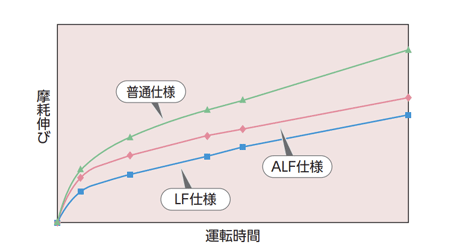
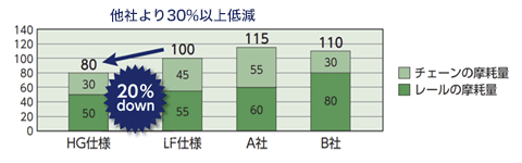
- 4. Applicable: Low Friction / Wear resistant (LFW, LFG, LFB) specifications, low friction (NLF, WR) specifications, Low Friction / Anti-Wear (HG) specifications, antibacterial and anti-fungal (MWS) specifications.
- 5. M-rail and SJ-CNO are wearstrip designed exclusively for dry conditions.
- 6. When water-lubricated, stainless steel pin types wear and elongate faster than plastic pin types.
- 7. Depending on the type of transported item, the value of (μ2) may be greater and adhesion may occur. We recommend measuring the dynamic friction coefficient for each transport.
Table 4. Coefficient of rolling friction between conveyed object and Plastic Roller (μ3)
| Target chain | Rolling friction coefficient |
|---|---|
| Accumulation chain TTPDH-LBP type Curved accumulation chain TPUS-LBP type, TPUS-Y-LAP-LFB-MFR type |
0.10 |
| Curved accumulation chain TPUS-Y-LAP type, TP-30UTW-LAP type, TP-36UTW-LAP type | 0.07 |
Table 5. Angle coefficient (αL) and length coefficient (αS) when using curved wearstrip
| Top Plate Material | Lubrication condition | Side bending angle | |||||||
|---|---|---|---|---|---|---|---|---|---|
| 30° | 60° | 90° | 120° | 150° | 180° | ||||
| Angle coefficient (αL) | Stainless steel or steel | No lubrication/water lubrication | 1.20 | 1.45 | 1.75 | 2.10 | 2.50 | 3.00 | |
| Soapy water lubrication | 1.10 | 1.25 | 1.35 | 1.50 | 1.70 | 1.85 | |||
| oil lubrication | 1.10 | 1.25 | 1.35 | 1.50 | 1.70 | 1.85 | |||
| Polyacetal | Standard Series Note 3 | No lubrication/water lubrication | 1.15 | 1.30 | 1.50 | 1.70 | 1.90 | 2.20 | |
| Soapy water lubrication | 1.10 | 1.15 | 1.25 | 1.35 | 1.50 | 1.60 | |||
| Low friction specification Note 4 | No lubrication/water lubrication | 1.10 | 1.25 | 1.35 | 1.50 | 1.70 | 1.85 | ||
| Soapy water lubrication | 1.10 | 1.15 | 1.25 | 1.35 | 1.50 | 1.60 | |||
| CB | No lubrication/water lubrication | 1.10 | 1.25 | 1.35 | 1.50 | 1.70 | 1.85 | ||
| Soapy water lubrication | - | - | - | - | - | - | |||
| ALF | No lubrication/water lubrication | 1.10 | 1.15 | 1.25 | 1.35 | 1.50 | 1.60 | ||
| Soapy water lubrication | 1.05 | 1.10 | 1.20 | 1.25 | 1.35 | 1.40 | |||
| KVNote)2 | No lubrication/water lubrication | 1.15 | 1.30 | 1.50 | 1.70 | 1.90 | 2.20 | ||
| Soapy water lubrication | 1.10 | 1.20 | 1.30 | 1.40 | 1.50 | 1.65 | |||
| DIA,MPD | No lubrication (dry) | 1.15 | 1.35 | 1.60 | 1.85 | 2.20 | 2.55 | ||
| HTW | No lubrication/water lubrication | 1.20 | 1.45 | 1.75 | 2.10 | 2.50 | 3.00 | ||
| Soapy water lubrication | 1.10 | 1.25 | 1.35 | 1.50 | 1.70 | 1.85 | |||
| MF | No lubrication (dry) | 1.15 | 1.35 | 1.55 | 1.75 | 2.05 | 2.35 | ||
| HS | No lubrication (dry) | 1.15 | 1.30 | 1.50 | 1.70 | 1.90 | 2.20 | ||
| Length factor (αS) | 0.5 | 1 | 1.6 | 2.1 | 2.6 | 3.1 | |||
Note)
- 1. Lubrication is recommended for curved conveyors where the chain and wearstrip slide against each other. Particularly for curved conveyors with a sideways angle of more than 90°, the chain or wearstrip may wear unevenly in a relatively short period of time, which may cause the chain to lift up. If lubrication is not possible, consider using corner discs to prevent sideways bending.
- 2. The heat resistance and high speed (KV) specifications are for normal temperatures. At high temperatures (over 50°C), please apply the values for steel or stainless steel without lubrication or with water lubrication.
- 3. Applicable to: Standard Series, Chemical resistant (Y), Conductive (E), Impact resistant (DIY), Metal detectable (MPW), UV resistant (UVR), and Plastic Crescent Chain.
- 4. Applicable: Low Friction / Wear resistant (LFW, LFG, LFB) specifications, low friction (NLF, WR) specifications, Low Friction / Anti-Wear (HG) specifications, antibacterial and anti-fungal (MWS) specifications.
Table 6. Angle coefficient (αc) when using a corner disc
| Target chain | Angle coefficient (αc) |
|---|---|
| TPUSR550 type TPUSR826 type TPUH-BO type TPUN555 type TPUN550-LH type TPUN535-LH type TP-UB36 type TP-50UNS type (including D76) |
Corner disc with bearing: 1.1 Corner disc without bearing: 1.15 |
Note)
- 1. αc is a coefficient used for curved conveyance by chains using corner discs, and is constant regardless of the lateral bending angle.
- 2. Plastic Crescent Chain TOS type uses sprockets at the corners. If there are bearings on the sprocket shaft, apply the values in the table above.
Step 5. Calculate chain tension and power requirements
5-1. Calculation of F for straight running
Note: SI units and gravity units
The formula is written in both SI units and gravity units. When calculating tension F in gravity units, weight in gravity units (kgf) is the same value as mass in SI units (kg).
Explanation of symbols
- F = tension acting on the chain kN{kgf}
- m1 = Approximate chain mass (kg/m)
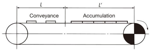
- L = length of conveying section (m)
- m2 = mass of material conveyed through the conveying section (kg/m)
- L' = Length of the accumulation section (m)
- m3 = Mass of material conveyed in the accumulator (kg/m)
- μ1 = Coefficient of dynamic friction between the chain and wearstrip (see Table 3)
- μ2 = Dynamic friction coefficient between the chain and the conveyed object in the accumulation section (see Table 3)
- μ3 = Coefficient of rolling friction between Plastic Roller and the conveyed object (see Table 4)
- αL = angle factor when using wearstrip (see Table 5)
- αC = angle factor when using corner discs (see Table 6)
- αS = length factor (see Table 5)
- θ = tilt angle (degrees)
- r = radius of lateral bending (m)
- P = required power (kW)
- V = Chain speed (m/min)
- ηNote) = Mechanical transmission efficiency of the drive unit
Note: Please check the drive unit used to determine transmission mechanical efficiency.
SI units (kN)
Tension acting on the chain
F = 9.80665 × 10⁻³ { (2.1m1 + m2) L・μ1 + (2.1m1 + m3) L'・μ1 + m3・L'・μ2 }
Required power
P = F・V 60η
Gravity unit (kgf)
Tension acting on the chain
F = (2.1m1 + m2) L・μ1 + (2.1m1 + m3) L'・μ1 + m3・L'・μ2
Required power
P = F・V 6120η
Note: When using an accumulation chain (TTPDH-LBP type, etc.), μ2 of μ3 Please change it to and calculate.
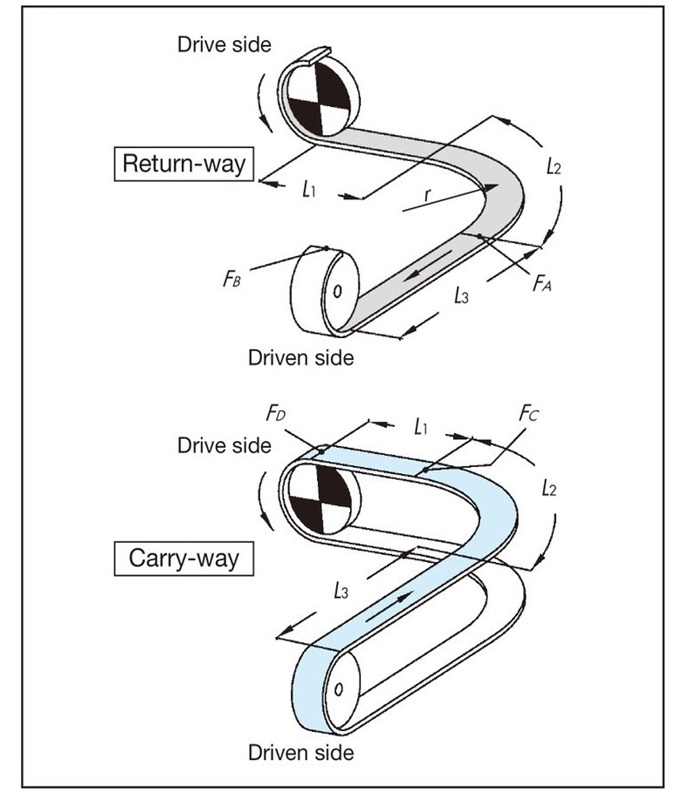
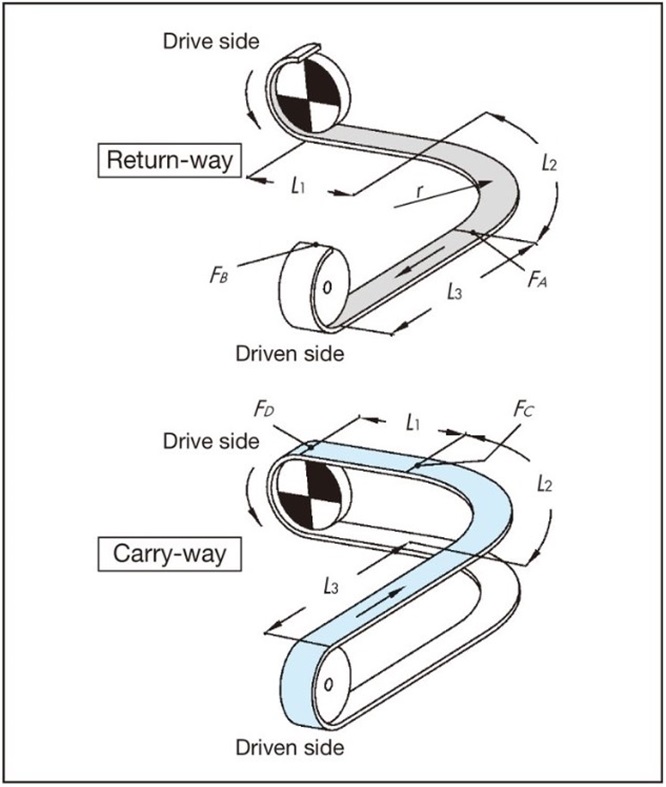
5-2. Calculation of F for curved conveyance (one curved section)
Basically, it is the same as for straight running. The tension acting on the corners is corrected by the angle coefficient.
An example calculation is shown for the conveying route in the diagram below. Lubrication is recommended for curved conveyance where the chain and wearstrip slide. In particular, when the lateral bending angle exceeds 90°, the chain or wearstrip may wear unevenly in a relatively short period of time, and the chain may lift off. If lubrication is not possible, consider using corner discs to prevent lateral bending.
F = 9.80665 × 10⁻³ ・FD (kN)
return-way tension
[A section tension: FA]
FA = m1(L1 + L2) μ1・αL 90°
L2 = r × αS 90°
[B part tension: FB]
FB = 1.1 ×(FA + m1・L3・μ1)
Transport side tension
[C part tension: FC]
FC ={FB + (m1 + m2) (L2 + L3) μ1 + m3 (L2 + L3) μ2}・αL 90°
L2 = r × αS 90°
[D part tension: FD]
FD = FC + {(m1 + m2) L1・μ1 + m3・L1・μ2}
Note
- 1. When using a curved accumulation chain (such as TPUS-LBP type), μ2 of μ3 Please change it to and calculate.
- 2. When using a corner disc in the corner section, use the corner disc angle coefficient αC instead of the angle coefficient αL.
5-3. Calculation of F for curved conveyance (two curved sections)
When sliding wearstrip or other device on a curved section, limit the number of 90-degree curves to two, as this may cause chain pulsation.
If you want to install more curved sections, consider dividing the conveyor or using a corner disc.
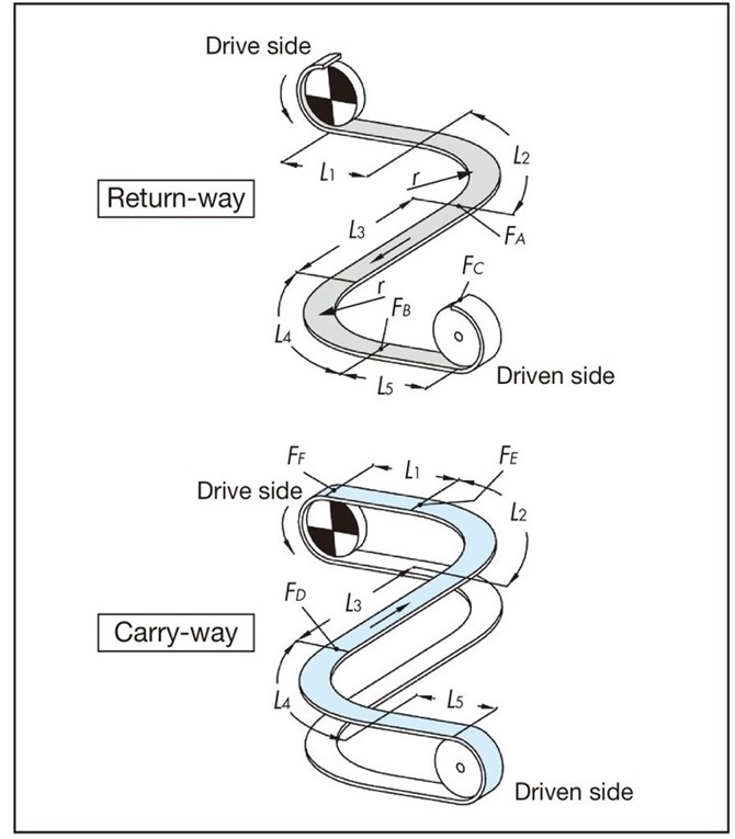
F = 9.80665 × 10⁻³ ・FF (kN)
return-way tension
[A section tension: FA]
FA = m1(L1 + L2) μ1・αL 90°
L2 = r × αS 90°
[B part tension: FB]
FB = {FA + m1(L3 + L4) μ1} αL 90°
L4 = r × αS 90°
[C part tension: FC]
FC = 1.1 × (FB + m1・L5・μ1)
Transport side tension
[D part tension: FD]
FD = {FC + (m1 + m2) (L4 + L5) μ1 + m3(L4 + L5) μ2}・αL 90°
L4 = r × αS 90°
[Tension at E section: FE]
FE = {FD + (m1 + m2) (L2 + L3) μ1 + m3(L2 + L3) μ2}・αL 90°
L2 = r × αS 90°
[F part tension: FF]
FF = FE + (m1 + m2) L1μ1 + m3・L1・μ2
Note
- 1. When using a curved accumulation chain (such as TPUS-LBP type), μ2 of μ3 Please change it to and calculate.
- 2. When using a corner disc in the corner section, use the corner disc angle coefficient αC instead of the angle coefficient αL.
5-4. Calculation of F for curved conveyance (horizontal drive)
| Applicable chain | TPUH-BO type (for horizontal transport), Plastic Crescent Chain (TORP type, TOSP type), Stainless steel Top chain (TO type, TU type) |
|---|
Basically, it is the same as for straight running. The tension acting on the corners is corrected by the angle coefficient.
A calculation example is shown for the transport route shown below.
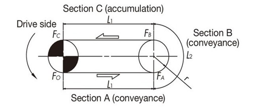
F = 9.80665 × 10⁻³ ・FC (kN)
[Tension at part A: FA] FA = (m1 + m2)・ L1 ・ μ1
[Tension at part B: FB] FB = {FA + (m1 + m2)・ L2 ・ μ1}・α C L2 = r ・α S 180°
[Tension at C section: FC] FC = FB + (m1 + m3)・ L1 ・ μ1 + m3 ・ L1 ・ μ2
5-5. Calculation of F for TTUP(T)-M type and TTUPM838H type curved conveyance (one curved section)
The coefficients in Table 7 are based on our internal experimental data. Differences may occur depending on the conditions of use, the shape and material (specifications) of the transported items.
Use each coefficient for tension calculations.
F = 9.80665 × 10⁻³ ・FD (kN)
return-way tension
[A section tension: FA]
FA = m1(L1 + L2) μ1・αL 90°
L2 = r × αS 90°
[B part tension: FB]
FB = 1.1 ×(FA + m1・L3・μ1)
Transport side tension
[C part tension: FC]
FC = {FB + (m1 + m2) L2・(μ1 + μ4) + (m1 + m2)・L3・μ1 + m3
(L2 + L3)・μ2} × αL 90°
L2 = r × αS 90°
[D part tension: FD]
FD = FC + {(m1 + m2) L1・μ1 + m3・L1・μ2}
Table 7. Magnet coefficient (μ4)
| Magnet Coefficient | ||
|---|---|---|
| Lubrication condition | No lubrication/water lubrication | |
| Top Plate Material | CB | 0.47 |
| ALF | ||
| HG | ||
5-6. Calculation of F for inclined conveyance
It is difficult to accurately determine the angle of the tilt limit due to the influence of speed, transported object, center of gravity, mass, conditions, etc.
Table 8 shows a guideline, but testing is required.
Table 8. Guide to inclined conveying angle
| Chain Material | No lubrication (dry) | Soapy water lubrication | oil lubrication |
|---|---|---|---|
| Steel | 10 degrees | - | 6 degrees |
| Standard Series (polyacetal) | 5 degrees | 3 degrees | - |
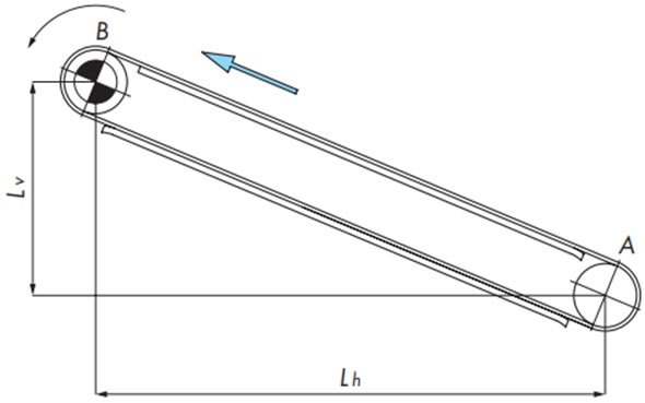
F = 9.80665 × 10⁻³ ・FB (kN)
return-way tension
[A section tension: FA]
FA = 1.1m1 (Lh・μ1 - Lv)
If FA < 0, then FA = 0
Chain tension
F = FB
Transport side tension
[B part tension: FB]
FB = FA + {(m1 + m2) (Lh・μ1 + Lv)}
Step 6. Determine the chain format
Select Top chain with Maximum allowable load greater than the tension (F) acting on the chain.
Calculate Maximum allowable load by referring to Allowable load graph and taking into account the conveyor speed and ambient temperature.
Please refer to each product page for Allowable load graph.
F ≦ Maximum allowable load (taking into account speed and temperature)
If Maximum allowable load is insufficient, you can narrow the top plate width and increase the number of chains, or connect a shorter conveyor.
Alternatively, choose a chain with a higher Maximum allowable load.
Please also consider the environment in which the conveyor will be used when deciding on the chain type.