technical data Drive chain Roller Chain Selection
6. allowable tension selection method
This is a selection method using Maximum allowable load.
1. Speed Considerations
This selection method is for when roller chains are used within the speed range shown in Table 1. If the chain is to be used above the upper speed limit in the table, please use the general selection method.
| Pitch mm |
Upper speed limit m/min |
|---|---|
| Less than 12.70 | 120 |
| 12.70 | 100 |
| 15.875 | 90 |
| 19.05 | 80 |
| 25.40 | 70 |
| 31.75 | 60 |
| 38.10 | 50 |
| 44.45 | 50 |
| 50.80 | 50 |
| 57.15 | 40 |
| 63.50 | 40 |
| 76.20 | 40 |
| 101.60 | 30 |
| 127.00 | 30 |
The maximum speed for Poly-steel chain is 70 m/min.
2. Considering impact
In harsh conditions, such as transmissions with large impacts, especially transmissions with large loads or transmissions where lateral loads may be present, please use F-type coupling links or 2-pitch offset links.
3. Strength of connecting links and offset links
When using M-type connecting links or offset links with the roller chains shown in Tables 2 and 3, multiply Maximum allowable load by the percentage shown in the table.
| RS roller chain | RS15, RS25, RS37, RS38, RS41, BF25-H |
80% |
| RS roller chain BS/DIN standard |
RF06B, RS56B, RS56B |
80% |
| Cold-resistant roller chain KT specifications |
All sizes | 80% |
| Offset Link | |||
|---|---|---|---|
| 1 pitch | 2 pitch | 4 pitch | |
| RS roller chain | 65% | 100% | - |
| RS roller chain BS/DIN standard |
60% | 60% | - |
| Super chain | - | - | 85% |
| RS roller chain NP Series |
65% | - | - |
| RS roller chain NEP Series / APP Series |
65% | - | - |
| Low-noise chain | 65% | - | - |
4. Sprocket considerations
When using Heavy duty drive chain, the chain tension increases. Therefore, commercially available cast iron sprockets may not have sufficient rib and hub strength. Use a material equivalent to S35C or higher. RS sprockets are strong enough to handle Heavy duty drive chain. For Heavy duty drive chain use sprockets with hardened tooth tips.
Please also refer to the formulas (here), coefficients (here) used for chain selection, and how to calculate the moment of inertia (here).
Example of selection using allowable tension selection method
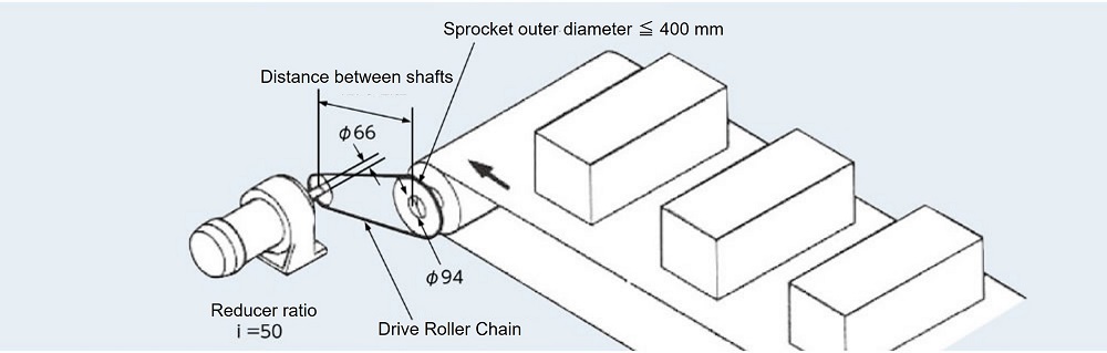
conditions
| Machine used | Conveyor Drive |
| Amount of material transported M | 6000kg |
| Transport speed V ℓ | 30m/min |
| Conveyor roll outer diameter | 380mm |
| Belt Thickness | 10mm |
| Conveyor roll rotation torque | 3.3kN・m{337kgf・m} |
| Motor specifications |
|
| Reducer reduction ratio | 1/50 (i = 50) |
| Drive shaft | Shaft diameter Φ66mm |
| driven axis | Shaft diameter Φ94mm |
| Center distance | 500mm |
| Driven sprocket outer diameter | ≦400mm |
| Start frequency | 10 times/day |
| Shock type | With some shock. |
| Soft start/stop | None |
| SI units |
|---|
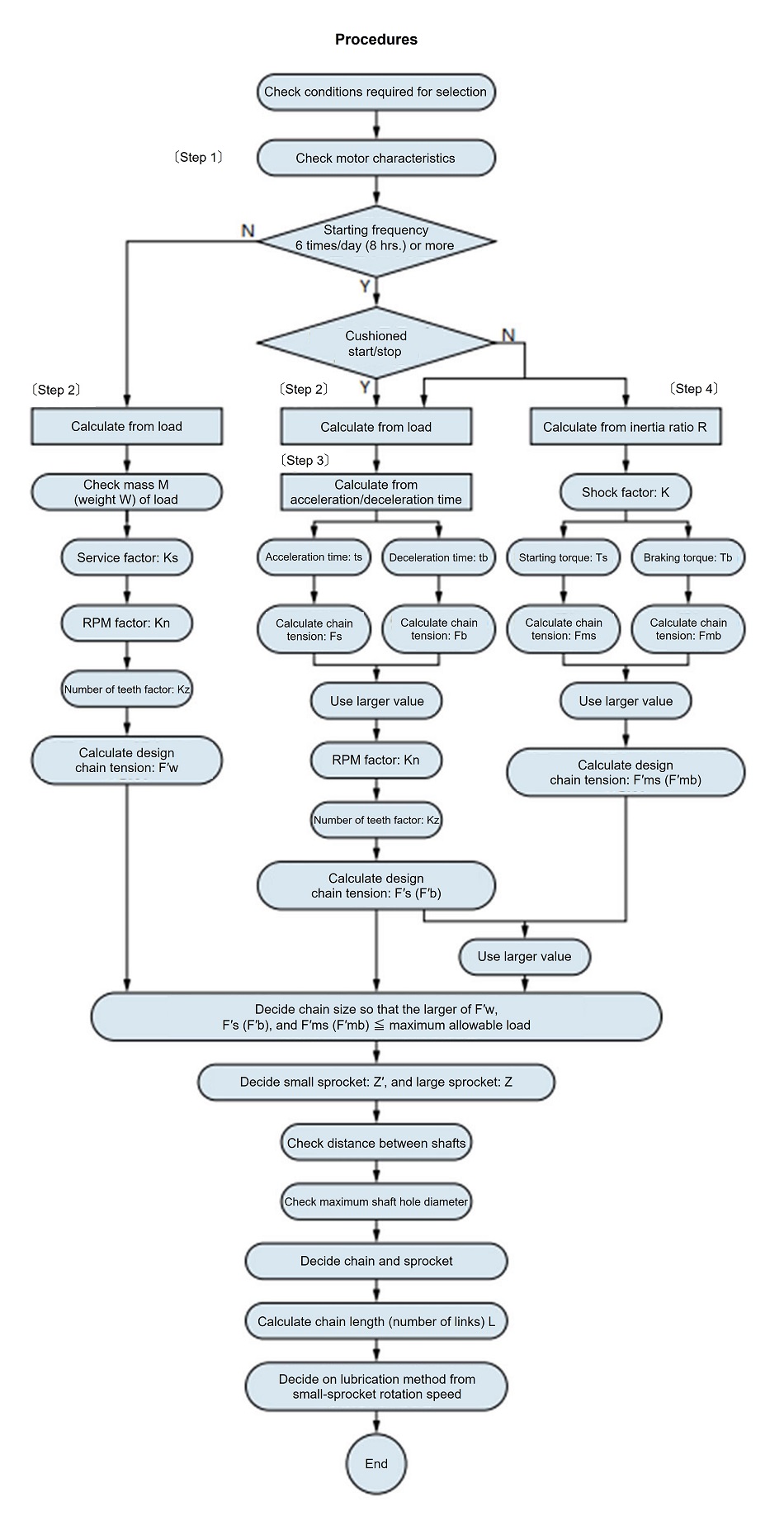
Step 1: Check the motor characteristics・Rated torque Starting torque ・Maximum (stall) torque Brake torque ・Motor moment of inertia Step 2 Calculate from the loadDriven shaft rotation speed Drive shaft rotation speed Chain reduction ratio = 23.9 36 = 1 1.51 PCD of driven sprocket d 2 = 400mm Select the chain provisionally. With some impact.... Service factor Ks = 1.3 Preliminary compensation chain tension = Fw × Ks = 16.5 × 1.3 = 21.5(kN) We tentatively select RS120-1, which Maximum allowable load of 30.4kN. Driven sprocket outer diameter < 400mm 31T Number of teeth on drive sprocket = 31 1.51 = 21T PCD d = 255.63(mm) Chain speed =
P × Z' × n
1000
=
38.1 × 21 × 36
1000
Small sprocket rotation speed: 36 r/min, rotation coefficient Kn = 1.03 Number of teeth on small sprocket 21T....Tooth number factor Kz = 1.10 Chain tension Fw = Conveyor roll rotation torque x 1000 x
2
d 2
Correction chain tension F'w = Fw × Ks × Kn × Kz RS120-1 can be used Maximum allowable load of 30.4kN. Check the transport speed (selection condition: 30m/min) V ℓ = n 2 ×
(Conveyor roll outer diameter + 2 × Belt thickness) × π
1000
Step 3: Calculate from acceleration/deceleration timeSince the calculation in step 2 determined that the small sprocket (reducer output shaft sprocket) was RS120 21T, the following calculations will also select the same pitch and number of teeth. If the acceleration and deceleration times are known, then use those values in the calculations. Here, we will make the calculations under the assumption that the times are unknown. Acting torque Tm = Ts + Tmax 2 = 0.116 + 0.122 2 = 0.119 (kN・m) Load torque T ℓ = Fw ×
d
2 × 1000 × i
= 17.5 ×
255.63
2 × 1000 × 50
Motor shaft converted moment of inertia on the load side I ℓ Motor moment of inertia Im = 0.088 (kg・m 2) Motor acceleration time Motor deceleration time Since tb < ts, the chain tension Fb during deceleration is greater than the chain tension Fs during acceleration, so this will be adopted below. deceleration Chain tension during deceleration Correction chain tension If we consider RS140 18T (outer diameter 279mm d 1 = 255.98) and 27T (outer diameter 407mm d 2 = 382.88), which have the same PCD, they cannot be used as they violate the condition of driven sprocket outer diameter ≦ 400mm. The chain reduction ratio went from the required 3623.9 to 2618. RS140-1 cannot be used as it has Maximum allowable load of 40.2kN. RS140-SUP-1 can be used because it has Maximum allowable load of 53.9kN. The sprocket shaft hole diameter is maximum 89mm for 18T and maximum 103mm for 26T. Since the center distance is 500 mm, the number of sprocket teeth is 18T (d 1 = 255.98). Step 4 Calculate from inertia ratio RInertia ratio R = I ℓ Im = 0.044 0.088 = 0.5 Since there is play in the transmission....Shock factor K = 1.0 Starting torque Ts = 0.116(kN・m) Chain tension due to starting torque Brake torque Tb = 0.116(kN・m) Chain tension due to brake torque If Fmb > Fms, the larger Fmb is used. Compensating Chain Tension
Comparing (1), (2), and (3), (3) has the largest corrective chain tension. F'mb = 61.7 (kN), so RS120-3 (Maximum allowable load 76.0 kN), Since the center distance is 500 mm, the number of sprocket teeth is 21T (d 1 = 255.63). RS160 15T (outer diameter 269mm d 1 = 244.33) with the same PCD RS160-1 cannot be used as it has Maximum allowable load of 53.0kN. RS160-SUP-1 can be used because it has Maximum allowable load of 70.6kN. The sprocket shaft hole diameter is maximum 95mm for 15T and maximum 118mm for 23T. Since the center distance is 500 mm, the number of sprocket teeth is 15T (d 1 = 244.33). |
| {gravity unit} |
|---|
Step 1: Check the motor characteristics・Rated torque Starting torque ・Maximum (stall) torque Brake torque ・Motor GD 2 Step 2 Calculate from the loadDriven shaft rotation speed Drive shaft rotation speed Chain reduction ratio = 23.9 36 = 1 1.51 PCD of driven sprocket d 2 = 400mm Select the chain provisionally. With some impact.... Service factor Ks = 1.3 Provisional chain tension = Fw × Ks = 1690 × 1.3 = 2200 (kgf) We tentatively select RS120-1, Maximum allowable load of 3100 kgf. Driven sprocket outer diameter < 400mm 31T Number of teeth on drive sprocket = 31 1.51 = 21T PCD d = 255.63(mm) Chain speed =
P × Z' × n
1000
=
38.1 × 21 × 36
1000
Small sprocket rotation speed: 36 r/min, rotation coefficient Kn = 1.03 Number of teeth on small sprocket 21T....Tooth number factor Kz = 1.10 Chain tension Fw = Conveyor roll rotation torque x 1000 x
2
d 2
Correction chain tension F'w = Fw × Ks × Kn × Kz RS120-1 can be used Maximum allowable load of 3100 kgf. Check the transport speed (selection condition: 30m/min) V ℓ = n 2 ×
(Conveyor roll outer diameter + 2 × Belt thickness) × π
1000
Step 3: Calculate from acceleration/deceleration timeSince the calculation in step 2 determined that the small sprocket (reducer output shaft sprocket) was RS120 21T, the following calculations will also select the same pitch and number of teeth. If the acceleration and deceleration times are known, then use those values in the calculations. Here, we will make the calculations under the assumption that the times are unknown. Acting torque Tm = Ts + Tmax 2 = 11.9 + 12.5 2 = 12.2 (kgf・m) Load torque T ℓ = Fw ×
d
2 × 1000 × i
= 1790 ×
255.63
2 × 1000 × 50
Motor shaft conversion Load side GD 2 Motor GD2 GD2m = 0.352 (kgf・m 2) Motor acceleration time Motor deceleration time Since tb < ts, the chain tension Fb during deceleration is greater than the chain tension Fs during acceleration, so this will be adopted below. deceleration Chain tension during deceleration Correction chain tension If we consider RS140 18T (outer diameter 279mm d 1 = 255.98) and 27T (outer diameter 407mm d 2 = 382.88), which have the same PCD, they cannot be used as they violate the condition of driven sprocket outer diameter ≦ 400mm. The chain reduction ratio went from the required 3623.9 to 2618. RS140-1 cannot be used as it has Maximum allowable load of 4100 kgf. RS140-SUP-1 can be used because it has Maximum allowable load of 5500 kgf. The sprocket shaft hole diameter is maximum 89mm for 18T and maximum 103mm for 26T. Since the center distance is 500 mm, the number of sprocket teeth is 18T (d 1 = 255.98). Step 4 Calculate from inertia ratio RInertia ratio R = GD 2ℓ GD 2 m = 0.176 0.352 = 0.5 Since there is play in the transmission....Shock factor K = 1.0 Starting torque Ts = 11.9 (kgf・m) Chain tension due to starting torque Brake torque Tb = 11.9 (kgf・m) Chain tension due to brake torque If Fmb > Fms, the larger Fmb is used. Compensating Chain Tension
Comparing (1), (2), and (3), (3) has the largest corrective chain tension. F'mb = 6330 (kgf), so RS120-3 (Maximum allowable load 7550 kgf), Since the center distance is 500 mm, the number of sprocket teeth is 21T (d 1 = 255.63). RS160 15T (outer diameter 269mm d 1 = 244.33) with the same PCD RS160-1 cannot be used as it has Maximum allowable load of 5400 kgf. RS160-SUP-1 can be used because it Maximum allowable load of 7200 kgf. The sprocket shaft hole diameter is maximum 95mm for 15T and maximum 118mm for 23T. Since the center distance is 500 mm, the number of sprocket teeth is 15T (d 1 = 244.33). |
Selection results
| conditions | procedure | Model number | Sprocket | Number of links | Lubrication type |
|---|---|---|---|---|---|
| Start frequency less than 6 times | Step 2 | RS120-1 | 21T×31T | 54 Links | AII |
| Start frequency: 6 or more times Cushion start available. |
Step 3 | RS120-2 | 21T×31T | 54 Links | AII |
| RS140-SUP-1 | 18T×26T | 46 Links | B | ||
| Start frequency: 6 or more times No cushion start. |
Step 3 Step 4 |
RS120-3 | 21T×31T | 54 Links | AII |
| RS120-SUP-2 | B | ||||
| RS160-SUP-1 | 15T×23T | 40 Links | B |
- Notes: 1. Lubrication type: Please check kW ratings table for each chain size and specifications.
- 2. Adjustment of the center distance is required for all shafts.
Please also refer to the formulas (here), coefficients (here) used for chain selection, and how to calculate the moment of inertia (here).

