technical data Drive chain Chain Selection
Calculation formula required for selection
Symbols and units used in formulas
| symbol | Explanation | SI units | {gravity unit} |
|---|---|---|---|
| αb | Load deceleration | m/s2 | m/s2 |
| αs | Load acceleration | m/s2 | m/s2 |
| C | Axle distance expressed in number of links | - | - |
| C′ | conveyor length | m | m |
| d | Pitch circle diameter of the reducer output shaft sprocket | mm | mm |
| d1 | Pitch diameter of small sprocket | mm | mm |
| d2 | Large sprocket pitch diameter | mm | mm |
| D | Drum outer diameter | mm | mm |
| Fb | Chain tension during deceleration | kN | kgf |
| F'b | Corrective chain tension during deceleration | kN | kgf |
| FC | Chain tension of the carriage drive | kN | kgf |
| F'C | Compensation chain tension for carriage drives | kN | kgf |
| Fℓ | Chain tension due to load (actual load) torque | kN | kgf |
| F'ℓ | Corrected chain tension due to load (actual load) torque | kN | kgf |
| Fm | Chain tension by motor rated output (kW) | kN | kgf |
| F'm | Compensating chain tension from the prime mover side | kN | kgf |
| Fms | Chain tension due to starting torque of prime mover | kN | kgf |
| F'ms | Correction of chain tension by starting torque of prime mover | kN | kgf |
| Fmb | Chain tension due to engine brake torque | kN | kgf |
| F'mb | Correction of chain tension by motor brake torque | kN | kgf |
| FS | Chain tension during acceleration | kN | kgf |
| F'S | Corrective chain tension during acceleration | kN | kgf |
| FW | Chain tension due to load (actual load) | kN | kgf |
| F'W | Corrected chain tension from load (actual load) | kN | kgf |
| f1 | Friction coefficient between roller and rail (with lubrication 0.14, without lubrication 0.21) | - | - |
| G | Standard gravitational acceleration G = 9.80665m/S 2 | - | - |
| i | For example, if the speed ratio is 1/30, then i = 30. | - | - |
| Iℓ{GD2ℓ} | Load moment of inertia converted to motor shaft | kg・m2 | kgf・m2 |
| Im{GD2m} | Moment of inertia of the prime mover shaft | kg・m2 | kgf・m2 |
| K | Impact Factor | - | - |
| Kn | Rotation Factor | - | - |
| Ks | Service factor | - | - |
| Ku | Unbalanced Load Factor | - | - |
| Kv | Pin gear speed coefficient | - | - |
| Kz | Tooth number coefficient | - | - |
| L | Chain length (number of links) | - | - |
| m | Chain unit mass {weight} | kg/m | kgf/m |
| M{W} | Load mass {weight} | kg | kgf |
| n | Rotational speed of the small sprocket when calculating the chain speed | r/min | rpm |
| n1 | Motor shaft rotation speed | r/min | rpm |
| n2 | Rotational speed of the load shaft (rotational speed of the driven shaft) | r/min | rpm |
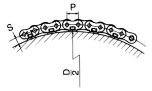
| P | Chain pitch | mm | mm |
| R | inertia ratio | - | - |
| S | Attachment height of RS attachment chain (distance from drum mounting surface to chain pitch center) | mm | mm |
| tb | Deceleration time | s | s |
| tS | Acceleration Time | s | s |
| Tb | Braking torque of the prime mover | %(kN・m) | %(kgf・m) |
| Tmax | Maximum (stall) torque of the prime mover | %(kN・m) | %(kgf・m) |
| TS | Starting torque of the prime mover | %(kN・m) | %(kgf・m) |
| Tℓ | Load Torque | kN・m | kgf・m |
| Tm | Acting Torque | kN・m | kgf・m |
| Tn | Rated torque of the prime mover | kN・m | kgf・m |
| V | Chain Speed | m/min | m/min |
| Vℓ | Load Speed | m/min | m/min |
| Z | Number of teeth on large sprocket | - | - |
| Z′ | Number of teeth on small sprocket | - | - |
| ω | Angular velocity of the prime mover shaft | rad/min | rad/min |
| ωb | Angular deceleration of the prime mover shaft | rad/s2 | rad/s2 |
| ωS | Angular acceleration of the prime mover shaft | rad/s2 | rad/s2 |
calculation formula
- 1. All selections are made assuming a transmission efficiency including the chain of η = 1.
- 2. For the tension and power transmission kW used in the selection, use the values calculated in items 13 and 14 of the table.
| item | SI units | {gravity unit} |
|---|---|---|
|
1. Chain length (number of links): L |
When using a two-shaft winding transmission
|
|
|
Pin gear drive |
When using a chain with an attachment wound around the outside of the drum L = 180° tan-1 P D + 2S
|
|
|
2. Chain speed: V |
V = P × Z' × n 1000 (m/min) |
|
|
3. Chain tension at rated motor output (kW) and rated rotation speed: Fm |
Fm = 60 × kW V (kN) |
Fm = 6120 × kW V (kgf) |
|
4. Load moment of inertia I(GD 2)of |
Iℓ = M × V 2πn1 2 (kg・m2) |
GD2ℓ = W × V πn1 2 (kgf・m2) |
|
5. Rated torque of the prime mover: Tn |
Tn = 9.55 × kW n1 (kN・m) |
Tn = 974 × kW n1 (kgf・m) |
|
6. Working torque: Tm |
Tm =
Ts(%) + T max (%)
2 × 100
× Tn (kN・m) |
Tm =
Ts(%) + T max (%)
2 × 100
× Tn (kgf・m) |
|
7. Chain tension due to starting torque: Fms |
Fms =
Ts(%) × i
{d/(2 × 1000)} × 100
× Tn × 1(kN) |
Fms =
Ts(%) × i
{d/(2 × 1000)} × 100
× Tn × 1(kgf) |
|
Chain tension due to brake torque: Fms |
Fmb =
T b (%) × i
{d/(2 × 1000)} × 100
× Tn × 1.2*(kN) * is a constant |
Fmb =
T b (%) × i
{d/(2 × 1000)} × 100
× Tn × 1.2*(kgf) * is a constant |
8. Acceleration time: ts |
ts = (Im + Iℓ) × n1 9550 × (Tm - Tℓ) (s) |
ts = (GD2m + GD2ℓ) × n1 375 × (Tm - Tℓ) (s) |
9. Deceleration time: t b ±: For negative loads such as hanging loads |
tb = (Im + Iℓ) × n1 9550 × (Tb ± Tℓ) (s) |
tb = (GD2m + GD2ℓ) × n1 375 × (Tb ± Tℓ) (s) |
10. Acceleration
Assumes straight line acceleration. If not, calculate at maximum acceleration. |
Linear motion (load acceleration) αs = V ℓ ts × 60 Rotational motion (angular velocity of the prime mover shaft) ω = 2 π × n1 Rotational motion (angular acceleration of the prime mover shaft) ωs = ωts × 60 |
|
11. Deceleration
Assumes straight line acceleration. If not, calculate at maximum deceleration. |
Linear motion (load deceleration) αb = V ℓ tb × 60 Rotational motion (angular velocity of the prime mover shaft) ω = 2 π × n1 Rotational motion (angular deceleration of the prime mover shaft) ωb = ωtb × 60 |
|
12. Chain tension during acceleration: Fs |
Linear motion Fs = M × αs 1000 + Fw Rotational motion Fs = I ℓ × ωs × i 1000 × d 2 × 1000 + Fw |
Linear motion Fs = M × αs G + Fw Rotational motion Fs = GD 2ℓ /4 × ωs × i d 2 × 1000 × G + Fw |
Chain tension during deceleration: Fb |
Linear motion Fb = M × αb 1000 + Fw Rotational motion Fb = I ℓ × ωb × i 1000 × d 2 × 1000 + Fw |
Linear motion Fb = M × αb G + Fw Rotational motion Fb = GD 2ℓ /4 × ωb × i d 2 × 1000 × G + Fw |
13. Correction kW (for general selection) |
Correction kW = Prime mover rated kW × Ks (kW) | |
14. Compensation chain tension |
||
Correction chain tension from the prime mover: F'm |
F'm = Fm × Ks × Kn × Kz (kN) {kgf} | |
Corrected chain tension from starting torque: F'ms |
F'ms = Fms × K × Kn × Kz (kN) {kgf} | |
Correction chain tension from stall torque: F'mb |
F'mb = Fmb × K × Kn × Kz (kN) {kgf} | |
Compensation chain tension of the carriage drive: F'c |
F'c = Fc × Ks × Kn × Kz (kN) {kgf} | |
Corrected chain tension during acceleration: F's |
F's = Fs × Kn × Kz (kN) {kgf} | |
Corrected chain tension during deceleration: F'b |
F'b = Fb × Kn × Kz (kN) {kgf} | |
Corrected chain tension from load: F'w |
F'w = M × Ks × Kn × Kz × G 1000 (kN) |
F′w = W (or Fw) × Ks × Kn × Kz (kgf) |
|
If the mass M {weight W} is unknown, calculate the shaft torque T = Tn × i (kN・m) {kgf・m} from the rated torque Tn of the prime mover, |
||
15. Inertia ratio: R |
R = Iℓ Im |
R = GD2ℓ GD2m |
16. Conversion of moment of inertia (I) and flywheel effect (GD 2) |
1kg・m2...(I) | 4kgf・m2...(GD2) |
The chain tensions in the above formulas are all for use with a single chain.
When using two or more chains, calculate the tension per chain by multiplying it by the unbalanced load coefficient Ku (Table 4).
Unbalanced load factor Ku
When using two or four chains for lifting or driving a cart, the tension acting on the chains will not be uniform.
This is used as a guideline for left-right imbalance when calculating the tension acting on each chain by multiplying it by the unbalance load coefficient Ku below.
(Example) Unbalanced load coefficient per unit in a four-strand suspension
Ku = 0.6 × 0.6 = 0.36
| 2 bottles | 0.6 |
|---|---|
| 4 pieces | 0.36 |

