technical data Drive chain Roller Chain Selection
2. Coefficients used for selection
multiple strand factor
The power transmission capacity of multiple strand roller chain cannot be expected to be No. of strands of that of single strand roller chain, because the load on each strand of the chain is not equally distributed.
Therefore, the power transmission capacity of multiple strand roller chain is calculated by multiplying the power transmission capacity of single strand roller chain by multiple strand factor.
| No. of strands roller chain strands | multiple strand factor |
|---|---|
| 2 rows | 1.7 |
| 3 rows | 2.5 |
| 4 rows | 3.3 |
| 5 rows | 3.9 |
| 6 rows | 4.6 |
Service factor Ks
The transmission capacity is based on the condition that the load fluctuation is small, so the transmission kW is corrected by Service factor Ks depending on the size of the load fluctuation.
Service factor Ks is determined based on Table 2, depending on the type of machine and prime mover.
Multiply the transmitted kW by Service factor to find design kW.
| Shock type | Examples of machines used | Type of engine | ||
|---|---|---|---|---|
| motor turbine |
Internal Combustion Engines | |||
| Fluid Coupling Attached |
Fluid Coupling none |
|||
| Smooth transmission | Belt conveyors and chain conveyors with minimal load fluctuations Centrifugal pumps, centrifugal blowers, general textile machinery, General machinery with little load fluctuation |
1.0 | 1.0 | 1.2 |
| A bit of a shock Accompanying transmission |
Centrifugal compressors, marine propulsion units, conveyors with slight load fluctuations, Automatic furnaces, dryers, crushers, general machine tools, compressors, General construction machinery, general paper-making machinery |
1.3 | 1.2 | 1.4 |
| A big shock Accompanying transmission |
Presses, crushers, construction and mining machinery, vibrating machines, Oil well drills, rubber mixers, rolls, roll guns, General machinery subject to reverse or shock loads |
1.5 | 1.4 | 1.7 |
Rotation factor Kn and tooth number factor Kz
Table 3 Rotation coefficient Kn and tooth number coefficient Kz
| Rotational speed r/min | Rotation coefficient Kn |
|---|---|
| Under 27 | 1.00 |
| 27以上37未満 | 1.03 |
| 37以上50未満 | 1.07 |
| 50以上70未満 | 1.10 |
| 70以上100未満 | 1.14 |
| 100以上150未満 | 1.19 |
| 150以上300未満 | 1.27 |
| 300以上500未満 | 1.34 |
| 500以上1000未満 | 1.44 |
| 1000以上2000未満 | 1.54 |
| 2000以上4000未満 | 1.65 |
| Number of teeth | Tooth number factor Kz |
|---|---|
| 9以上12未満 | 1.16 |
| 12以上15未満 | 1.14 |
| 15以上18未満 | 1.12 |
| 18以上24未満 | 1.10 |
| 24以上30未満 | 1.08 |
| 30以上38未満 | 1.06 |
| 38以上47未満 | 1.04 |
| 47以上60未満 | 1.02 |
| 60 and over | 1.00 |
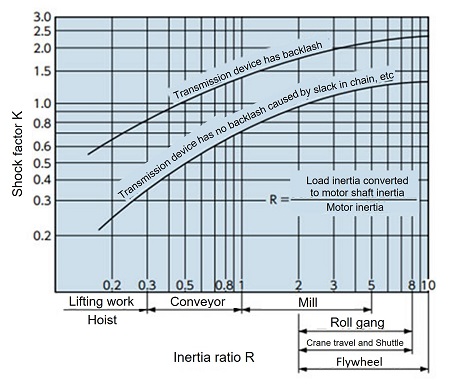
Impact coefficient K
This is a constant determined by the ratio of the inertia moments (I ratio, GD2 ratio) between the prime mover and the load when converted to the same shaft, and the amount of play in the transmission device.
When the inertia ratio R > 10, R = 10
If the inertia ratio R < 0.2, set R = 0.2.
If I or GD2 of the prime mover or load is unknown, use the value of R in Figure 1.
Figure 1 Impact coefficient K
Unbalanced load factor Ku
When using two or four chains for lifting or driving a cart, the tension acting on the chains will not be uniform.
This is used as a guideline for left-right imbalance when calculating the tension acting on each chain by multiplying it by the unbalance load coefficient Ku below.
(Example) Unbalanced load coefficient per unit in a four-strand suspension
Ku = 0.6 × 0.6 = 0.36
| 2 bottles | 0.6 |
|---|---|
| 4 pieces | 0.36 |

