technical data Cable Carrier (CABLEVEYOR)- Handling Cable Carrier (CABLEVEYOR)- Installation, Maintenance, and Precautions
Installation and maintenance
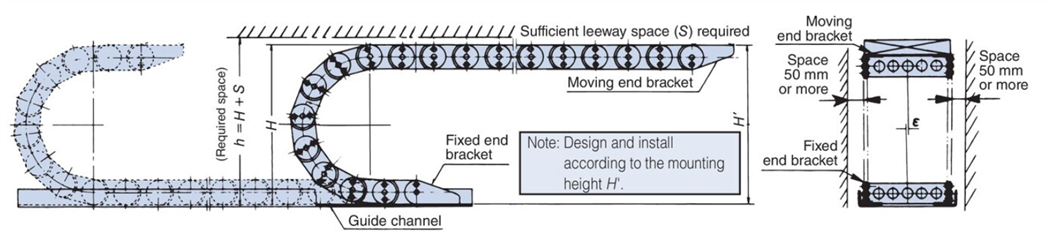
required space
Cable Carrier (CABLEVEYOR) has a slight bulge to compensate for deflection caused by the main body and cable mass, so please install it at the installation height H' rather than the total height H of Cable Carrier (CABLEVEYOR). Bulge and deflection will occur in the free span depending on the usage conditions and atmosphere. Please ensure the required space by referring to the diagram above. If there are no interfering objects, there will generally be no problems.
Also, vibrations may occur if the operating speed increases, so if the operating speed exceeds 70% of the maximum allowable speed, double the S dimension.
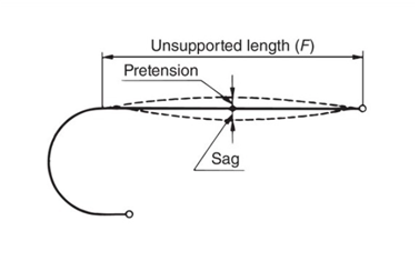
Also, as the free span will sag during use, please leave some space around the inner circumference of Cable Carrier (CABLEVEYOR).
| Variety/Size | ε or less | S | H' |
|---|---|---|---|
| TKP13H10,TKP17H11,TKP18H14/15,TKP25H15 | 3 | 50 | H+(10~30) |
| TKP35H22,TKP45H25,TKUA45H26 | 4 | 100 | |
| TKP Series other than those listed above, TKUA55H38, TKUA66H44 | 6 | 100 | |
| TKC type, TKA type | 6 | 100 | |
| TKMK type, TKMT type | 6 | 100 | |
| TKR15H22 | 6 | 100 | |
| TKR20H28,TKR26H40,TKR28H52,TKR37H28 | 6 | 100 | H+(30~50) |
| TKQ Series | 6 | 100 | H+(10~30) |
| TK070,TKS070 | 4 | 100 | H+10 |
| TK095,TKS095 | 6 | 100 | |
| TK130 | 8 | 100 | |
| TK180 | 10 | 100 | |
| TKH250 | 15 | 100 | H+30 |
*A straight specification (special type) that eliminates the bulge of Cable Carrier (CABLEVEYOR) is also available. Please refer to the special type specification page.
Cable Carrier (CABLEVEYOR) carrier guide
Cable Carrier (CABLEVEYOR) require guide channel. Refer to the table below to make them out of steel plates or angles.
The area where Cable Carrier (CABLEVEYOR) enters and exits should be chamfered or sloped to allow for smooth movement.
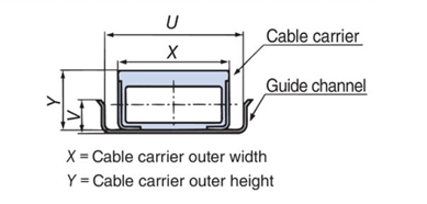
X = outer width of Cable Carrier (CABLEVEYOR), Y = outer height of Cable Carrier (CABLEVEYOR)
| Variety/Size | U | V |
|---|---|---|
| TKP13H10,TKP17H11,TKP18H14/15,TKP25H15 | X+10 | Y/2 or greater |
| TKP35H22,TKP45H25,TKUA45H26 | X+15 | |
| TKP Series other than those listed above, TKUA55H38, TKUA66H44 | X+20 | |
| TKC Series | X+20 | |
| TKMK type, TKMT type | X+20 | |
| TKR Series | X+20 | |
| TKQ Series | X+20 | |
| TK type, TKS type, TKH type | X+20 |
Lubricating
In principle, oiling of Cable Carrier (CABLEVEYOR) is not necessary, but if the TK, TKS, TKH, or TKV models are installed in an environment prone to rust, use grease to prevent rust on the links. The TKI model requires lubrication.
Special Use Precautions
- ■When a lateral load is applied, such as when using an overhead traveling crane, install support rollers or lateral guides to prevent the product from falling over.
- ■If there is external vibration from a manipulator, rock drill, etc., take measures to prevent the vibration from the machine from being transmitted to Cable Carrier (CABLEVEYOR) (such as using shock absorbers).
Important points to note when installing Gliding arrangement rails
If you are installing Gliding arrangement guide channel yourself, please note the following: We also offer Gliding arrangement guide channel that are easy to install.
■Terminology explanation
- Pushing: A force acts on the moving end fitting in the direction of bending radius, causing Cable Carrier (CABLEVEYOR) to move.
- Pulling direction: Cable Carrier (CABLEVEYOR) moves in the opposite direction to the above (pulling).
- Buckling: When Cable Carrier (CABLEVEYOR) is pushed and moves freely, the part of Cable Carrier (CABLEVEYOR) that slides on the rail bulges.
- H-rail: A rail that is installed in front of Fixed end bracket and has a shelf on which Cable Carrier (CABLEVEYOR) slides.
- U-rail: A rail that is installed behind Fixed end bracket and supports Cable Carrier (CABLEVEYOR) at floor level.
Material
Guide channel is used to regulate the thrust direction, and should be made of smooth steel plate, especially to reduce wear.
If paint is applied to the rails as an anti-rust treatment, the paint may peel off due to sliding, causing wear on Cable Carrier (CABLEVEYOR).
We recommend using galvanized steel or SUS304 for construction.
Also, when using outdoors, please make it from SUS304. Do not use our aluminum rails outdoors.
Rail installation accuracy
- - Horizontal deviation must be within 5mm in either direction per 5m, and the entire structure must not be inclined linearly in one direction.
- - Horizontal deviation must be within 3mm on either side per 5m, and the entire structure must not bend linearly in one direction.
Precision of fittings on both ends
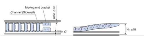
| Moving end side | Installation height | Within ±10mm across the entire rail |
|---|---|---|
| Width direction (thrust direction) deviation | Within ±3mm across the entire rail sidewall | |
| Parallelism | Within ±3° across the entire range relative to the rail sidewall |
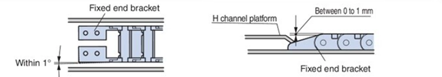
| Fixed end side | Installation height | The top surface of Fixed end bracket is within 0 to 1 mm of the shelf part of the H rail |
|---|---|---|
| Parallelism | Within 1° to the rail side wall |
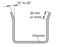
Taper angle of the rail top surface
The opening at the top of the rail should be angled outward to allow Cable Carrier (CABLEVEYOR) to enter the rail smoothly. The bending angle should be around 15 to 20 degrees and the length should be 30 mm or more.
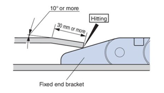
Structure of Fixed end bracket and rail transition area
To ensure smooth transfer of Cable Carrier (CABLEVEYOR), the H-rail transition section should be inclined. The shape should be inclined at an angle of 10° or more, with a length of 30 mm or more, and the rail end should be installed so that it touches Fixed end bracket.
If you use our dedicated aluminum rail, please chamfer the end surface to C2 before installation.
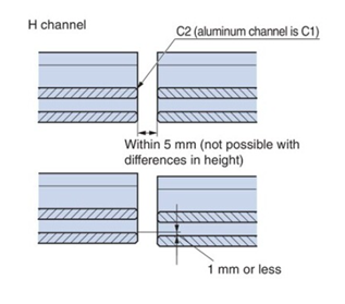
Rail joint processing
■H rail
Bend the ends of the joints on both sides outward to avoid any snags.
The shelves that slide must be tightly fitted and have no steps. If there is a gap at the joint, it must be within 5 mm, with a C2 chamfer and no steps.
When using our dedicated aluminum rails, chamfer the sliding surface to C1.
■U-rail
Bend the ends of the joints on both sides outward to avoid any snags.
The bottom surface should be installed so that the step is within 1 mm, and no processing such as chamfering is required, but the surface should be flat and free of burrs and wavy cut edges.
Overall length of cable/hose
Cable Carrier (CABLEVEYOR) body has clearance at the connecting parts (between the link pins and pin holes), and when tension is generated it will be longer than the basic length, so please prepare the total length of the cable hose etc. with some leeway and adjust it on the actual product. The amount of elongation can be up to approximately 0.2 to 0.6% of the total length, so please be careful with long strokes.
Examples of problems caused by construction defects
- ■ There is a step at the joint of the side wall
The bent part of Cable Carrier (CABLEVEYOR) interferes with the step, causing damage and buckling of Cable Carrier (CABLEVEYOR), and wear due to sliding.
- ■ There is a step at the joint at the bottom of the rail
Steps on H-rails can cause abnormal wear, while large steps on U-rails can cause buckling and partial wear.
- ■ The rail is not installed horizontally.
This may result in buckling and increased rolling resistance.

