technical data Synchronous Belts and Belt Sprockets design data
Pulley and shaft connection
(1) Key locking method
This is a general method of keying using the fit dimensional tolerances and keyway tolerances for the shaft hole and shaft shown in the table below.
Please refer to the pulley Fit Bore which has standardized shaft hole, key and tap processing and can be ordered using only the model number.
- - For aluminum pulleys, use with keyway surface pressure of 80N/mm2 or less and in one direction of rotation.
- - When using in forward and reverse rotation, please use Lock Belt Sprockets.
(2) Fastening method using friction
Please refer to Lock Belt Sprockets available with integrated friction fasteners.
For Lock Belt Sprockets selection, refer to the S-type Lock Belt Sprockets and C-type Lock Belt Sprockets.
- ・Friction-type fasteners such as Lock Belt Sprockets apply strong surface pressure to the pulley body, so aluminum Lock Belt Sprockets are made from a high-strength aluminum alloy. Standard aluminum pulleys (pilot bore) cannot be machined to use friction-type fasteners (such as Power-Lock) as this may damage the pulley.
If you are using a friction-type fastener with an aluminum pulley, please use our Lock Belt Sprockets.
Shaft hole dimensions and tolerances
Shaft hole and shaft fit dimensional tolerance (JIS B0401)
| Dimensions range mm | Shaft hole dimensional tolerance | Shaft dimensional tolerance | ||
|---|---|---|---|---|
| H7 | H8 | h7 | h8 | |
| Over 3 and under 6 | + 12~0 | + 18~0 | 0~-12 | 0~-18 |
| Over 6 and under 10 | + 15~0 | + 22~0 | 0~-15 | 0~-22 |
| Over 10 and under 18 | + 18~0 | + 27~0 | 0~-18 | 0~-27 |
| Over 18 and under 30 | + 21~0 | + 33~0 | 0~-21 | 0~-33 |
| Over 30 and under 50 | + 25~0 | + 39~0 | 0~-25 | 0~-39 |
| Over 50 and under 80 | + 30~0 | + 46~0 | 0~-30 | 0~-46 |
| Over 80 and under 120 | + 35~0 | + 54~0 | 0~-35 | 0~-54 |
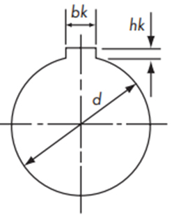
Keyway dimensions and tolerances
Typical dimensions and tolerances for Fit Bore shaft hole finished products are shown below for reference.
New JIS key Js9
| Shaft Hole Diameter | Key dimensions | Keyway Depth d + hk |
Groove Dimension Tolerance bk |
|---|---|---|---|
| 10 or more and 12 or less | 4×4 | d + 1.8 | 4±0.0150 |
| Over 12 and under 17 | 5×5 | d + 2.3 | 5±0.0150 |
| Over 17 and under 22 | 6×6 | d + 2.8 | 6±0.0150 |
| Over 22 and under 30 | 8×7 | d + 3.3 | 8±0.0180 |
| Over 30 and under 38 | 10×8 | d + 3.3 | 10±0.0180 |
| Over 38 and under 44 | 12×8 | d + 3.3 | 12±0.0215 |
| Over 44 and under 50 | 14×9 | d + 3.8 | 14±0.0215 |
| Over 50 and under 58 | 16×10 | d + 4.3 | 16±0.0215 |
| Over 58 and under 65 | 18×11 | d + 4.4 | 18±0.0215 |
| Over 65 and under 75 | 20×12 | d + 4.9 | 20±0.0260 |
| Over 75 and under 85 | 22×14 | d + 5.4 | 22±0.0260 |
| Over 85 and under 95 | 25×14 | d + 5.4 | 25±0.0260 |
Old JIS key E9
| Shaft Hole Diameter | Key dimensions | Keyway Depth d + hk |
Groove Dimension Tolerance bk |
|---|---|---|---|
| 10 or more and 13 or less | 4×4 | d + 1.5 | 4 +0.050 |
| Over 13 and under 20 | 5×5 | d + 2.0 | 5 +0.050 |
| Over 20 and under 30 | 7×7 | d + 3.0 | 7 +0.061 |
| Over 30 and under 40 | 10×8 | d + 3.5 | 10 +0.061 |
| Over 40 and under 50 | 12×8 | d + 3.5 | 12 +0.075 |
| Over 50 and under 60 | 15×10 | d + 5.0 | 15 +0.075 |
| Over 60 and under 70 | 18×12 | d + 6.0 | 18 +0.075 |
| Over 70 and under 80 | 20×13 | d + 6.0 | 20 +0.092 |
| Over 80 and under 95 | 24×16 | d + 8.0 | 24 +0.092 |
If you require keyway machining, please specify the dimensions and tolerances.
If no instructions are given, the tolerances in the table above will be used.
Pulley surface treatment
Various surface treatments are available depending on the application, so please consider them.
| Types of surface treatment | effect | Applicable material |
|---|---|---|
| Black Oxide | Rust prevention and decoration | Carbon steel for machine structures |
| electrogalvanizing | Rust prevention and decoration | Carbon steel for machine structures |
| Electroless nickel-phosphorus plating | Rust prevention and decoration | Carbon steel for machine structures |
| Anodized aluminum | Rust prevention | aluminum alloy |
| Hard anodized aluminum | Rust prevention and wear resistance | aluminum alloy |
Additional processing of standard stock items
The best way to machine the shaft hole of Belt Sprockets is to chuck the outer diameter of the teeth, but for Standard Stock Belt Sprockets, the outer diameter of the teeth and the outer diameter of the hub are machined to be precisely concentric, so we recommend chucking the outer diameter of the hub when machining the shaft hole.
In addition, when processing a DF type pulley, the flange will rotate, so please insert a setscrew into the tapped hole to prevent rotation.
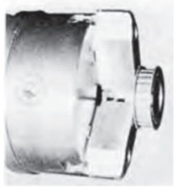
BF type chucking example
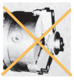
Be sure to avoid chucking the flange.
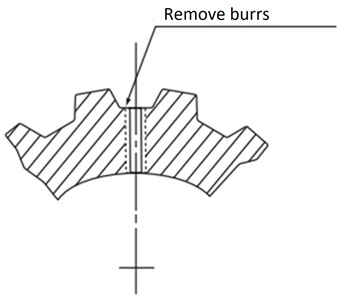
Tapping
When machining tooth root, be sure to remove any burrs. Be careful as burrs can damage the belt. (For pulleys with hubs, tap the hub.)