technical data Large size conveyor chain Smart Replaceable Series Handling
Before installation and removal
Precautions
- - When replacing sprockets or tooth replacements, the weight balance may be disturbed, causing the shaft to rotate or the sprocket or tooth replacement to fall. Always ensure that the equipment is securely supported and fixed before carrying out the work. Also, make sure to secure a safe work location and sufficient personnel before proceeding with the work.
- ・When removing the ring tooth type or block tooth type, if you are forced to burn off the bolt due to adhesion or corrosion of the transported material, remove any scratches or deposits on the mounting base seating surface with a file or grinder. It will be easier to remove the bolt if you place a backing plate (rod) with a smaller diameter than the bolt on the bolt and hit it with a hammer.
- - Particularly heavy sprockets and replacement teeth are equipped with hanging holes or eyebolt taps. Please securely fasten them with a sling or wire.
- - Thoroughly clean the sprocket mounting area on the shaft, the divisions of the sprocket body, and the mounting base. If there are any scratches, corrosion, or sticking in the conveying area, remove them with a file or grinder, and finish them smoothly.
Installation and removal procedures
1. Split type
Installation Procedure
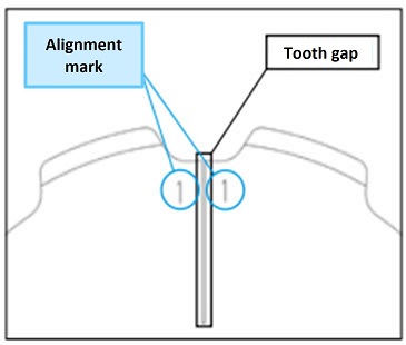
- 1. Assemble the split sprockets at the shaft mounting points.
At this time, assemble them so that the alignment marks on the teeth match. - 2. When the split sprockets are assembled, there is no gap on the mounting surface of the hub section, but there is a gap on the mounting surface of the teeth section, but this does not affect the meshing function.
- 3. Use the included spring washers on the bolts and tighten them securely with a torque wrench.
- 4. When attaching to the shaft, make sure that the divided surfaces are not misaligned.
Use the included spring washer to tighten the bolt evenly.
The tightening torque is as shown in the table below.
| Bolt size | M8 | M10 | M12 | M14 | M16 | M20 | M24 | M30 |
|---|---|---|---|---|---|---|---|---|
| Tightening torque [N・m] | 34 | 68 | 118 | 186 | 289 | 568 | 980 | 1960 |
*Please use the special bolts included with the sprocket.
*Although we use high-tensile bolts that are less likely to loosen in typical environments when used with the appropriate tightening torque,
If loosening is a concern, such as when subjected to strong vibrations, please take measures to prevent loosening, such as using a thread locker.
2. Ring replacement tooth type
Installation Procedure
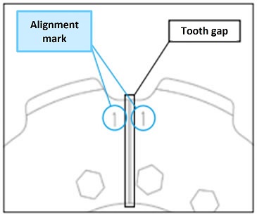
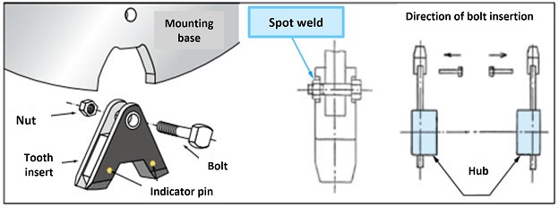
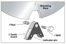
- 1. Place the replacement tooth on the mounting surface so that the alignment marks are aligned, and temporarily tighten it with the bolts, spring washers, and nuts.
- 2. Adjust the installation gap so that it is uniform. A good guideline for the gap is 1 to 3 mm. This gap will not cause any functional problems when it comes to engagement.
- 3. After installation, adjust the height of tooth root so that they are even.
- 4. Installation of bolts and nuts
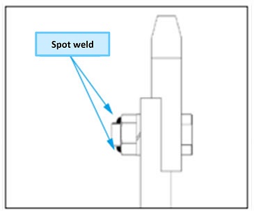
For spot welding mounting specifications
Apply spot welding to all nuts to prevent loosening. Apply spot welding in two places to all nuts to prevent loosening. Sprockets are expected to be used under harsh conditions such as vibration, corrosion, impact, and corrosive atmospheres. The tightening torque is as shown in the table below.Bolt size M8 M10 M12 M14 M16 M20 M24 M30 Tightening torque [N・m] 34 68 118 186 289 568 980 1960 *Please use the special bolts, nuts, and washers included with the replacement teeth.
In the case of HARDLOCK Nut mounting specifications
Tighten HARDLOCK Nut completely, ensuring they are tightened evenly.
For more secure tightening, please use a torque wrench.
The tightening torque is as shown in the table below.Size Convex nut (lower nut) Recessed nut (upper nut) Reference diagram of component configuration Tightening torque
*Units are in [N・m]Tightening torque
*Units are in [N・m]Ring replacement teeth M10 39 18~24 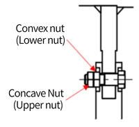
M12 68 27~39 M14 110 40~58 M16 170 70~100 M20 330 120~200 M24 570 160~300 M30 1130 270~440 *Please use the special bolts, HARDLOCK Nut, and washers included with the replacement teeth.
Draw a line with a marker so that it connects the bolt tip, HARDLOCK Nut, washer, and replacement teeth in a straight line.*Sprockets are intended for use in harsh environments such as those with vibration, shock, and corrosive atmospheres.
As this may cause bolts and nuts to loosen easily, please install markers to check for looseness on all mounting parts.
Removal Procedure
- 1. When removing the replacement tooth, remove the spot welds using a grinder or similar tool.
- 2. Remove the bolt and remove the replacement teeth. If you are unable to remove the nut due to adhesion of the transported material or corrosion of the sprocket, and are forced to take measures such as burning off the bolt, please remove any scratches or deposits on the mounting base seating surface with a file or grinder.
- ◎When replacing spot welding with HARDLOCK Nut
- 1. Remove any spot welds used to prevent the nuts from loosening using a grinder or similar tool.
- 2. Each tooth section is attached with a bolt and nut.
Loosen and remove each nut, making sure to securely fasten the teeth to prevent them from falling.
Especially for heavier sizes, there are suspension holes or eyebolt taps provided, so please secure them firmly using slings or wires. - 3. Remove the bolt and take out the replacement tooth.
- 4. Remove the remaining replacement teeth in the same manner.
- *When removing the nuts, it may be difficult to remove them due to the materials being transported becoming stuck or the sprocket being corroded.
If the bolts are damaged or have any residue on the seating surfaces, such as after burning them off, be sure to file them down.
Please smooth the surface using a grinder or similar tool.
The seating surfaces of bolts and nuts are structurally important elements of the ring-type sprocket series.
3. Block replacement tooth type
Installation Procedure
- 1. Apply the special adhesive (included) to the entire attachment area of the replacement tooth using a spatula or similar tool.
- 2. When assembling the tooth insert into the mounting base, make sure that the tooth insert is in contact with the bottom of the mounting base.
- 3. After checking the contact, tighten the bolts and nuts provided.
Note: When using with a bucket elevator, install the bolts from the inside to the outside of the conveyor.
- 4. All nuts should be secured with spot welding or HARDLOCK Nut to prevent loosening.
After confirming contact, tighten with the included bolts and nuts.
When using this in a bucket elevator, install the bolts from the inside to the outside of the conveyor. This will make work and inspection easier.
Please use a torque wrench when tightening the bolts. The tightening torque is as shown in the table below.
| Bolt size | M8 | M10 | M12 | M14 | M16 | M20 | M24 | M30 |
|---|---|---|---|---|---|---|---|---|
| Tightening torque [N・m] | 34 | 68 | 118 | 186 | 289 | 568 | 980 | 1960 |
*Please use the special bolts and nuts included with the replacement teeth.
In the case of HARDLOCK Nut mounting specificationsAfter confirming contact, tighten with the included bolts and nuts.
When using with a bucket elevator, install the bolts from the inside to the outside of the conveyor.
This makes work and inspection easier and prevents interference with attachments.
Please use a torque wrench when tightening bolts and nuts.
The tightening torque is as shown in the table below.
| Size | Convex nut (lower nut) | Recessed nut (upper nut) | Reference diagram of component configuration |
|---|---|---|---|
| Tightening torque *Units are in [N・m] |
Tightening torque *Units are in [N・m] |
Ring replacement teeth | |
| M10 | 39 | 18~24 | |
| M12 | 68 | 27~39 | |
| M14 | 110 | 40~58 | |
| M16 | 170 | 70~100 | |
| M20 | 330 | 120~200 | |
| M24 | 570 | 160~300 | |
| M30 | 1130 | 270~440 |
*Please use the special bolts and HARDLOCK Nut included with the replacement teeth.
5. Leave it like this for about 24 hours to allow the adhesive to dry.
Removal Procedure
- 1. When removing the replacement tooth, remove the spot welds using a grinder or similar tool.
- 2. Remove the bolt and remove the replacement teeth. If you are unable to remove the nut due to adhesion of the transported material or corrosion of the sprocket, and are forced to take measures such as burning off the bolt, please remove any scratches or deposits on the mounting base seating surface with a file or grinder.
- 3. Remove the bolt and remove the tooth replacement. Be careful not to let the tooth replacement fall out when removing the bolt.
- When replacing spot welding with HARDLOCK Nut
- 1. To remove the replacement tooth, remove the spot welds securing the nut using a grinder or similar tool, then loosen the nut and remove it.
Before loosening the nut, ensure that the replacement tooth is securely supported and fixed to prevent it from falling when loosened. Proceed with the work only after securing a safe workspace and sufficient personnel. - 2. If you are unable to remove the nut due to the transported object being stuck or the sprocket being corroded, and you are forced to burn off the bolt, scratches or debris on the mounting base surface may be present, so please remove them with a file or grinder.
- 3. Remove the bolt and take off the replacement tooth. Be careful to prevent the replacement tooth from suddenly coming loose and falling during this process.
Indicator pins Inspection
Indicator pins is an option that allows you to determine at a glance when it's time to replace your sprocket. For more information, please click here.
Please check Indicator pins as follows:
1. Inspection Procedure
- 1. If there is any residue on the side of the sprocket, remove it so that Indicator pins can be seen.
- 2. The limit of use is when the abrasion contacts Indicator pins.
- -Indicator pins are embedded in two places on each sprocket (approximately 0° and 180°) on the teeth.
- ・The position of Indicator pins varies depending on the model number. For products with a processed shaft hole, one checker's eye is embedded in the tooth part near the keyway.
2. Precautions
- - If the abrasion part comes into contact with Indicator pins and is continued to be used, the abrasion will be accelerated rapidly. This will also affect the wear of the chain, so please replace it as soon as possible.
- - If the wear on the face width exceeds 20%, even before it touches Indicator pins, replace the sprocket. Also, if wear is confirmed before it exceeds 20%, re-center the sprocket.
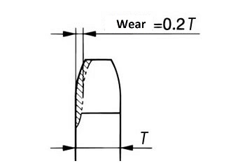
Wear on the sides of the teeth

