technical data linear actuator Linispeed Jack Selection
Requirements
Machines used: Table lifter, press fit machine, etc.
Layout.....
Synchronization of two jacks (separate motor drive or coupling with one motor), etc.
- Maximum load (W).....Weight of load or workpiece N
- Screw shaft speed (V).....Required speed of the jack m/min
- Stroke: Actual stroke used mm
Mounting type: Face mount, flange mounting, etc.
Installation condition...Base fixed, shaft end clevis, etc.

Time Cycle
Selection Procedure
1. Calculation of the correction load Ws
Considering the nature of the load, calculate the corrected load Ws by referring to Service factor (Table 1).
Corrected load Ws (kN) = Maximum load W (kN) × Service factor Sf
Table 1. Service factor Sf
| Load Nature | Usage example | Service factor |
|---|---|---|
| Smooth operation without shock Load inertia small |
Valve opening and closing Conveyor switching device |
1.0~1.3 |
| Operation with slight impact Load inertia medium |
Various moving devices Various lifter lifting |
1.3~1.5 |
| Operation with large shocks and vibrations Large load inertia |
Transporting objects by cart, positioning and maintaining rolling rollers | 1.5~3.0 |
Note: The above Service factor are general guidelines and should be determined taking into consideration the conditions of use.
2. Calculating the load W per jack
The load W per jack is calculated from the corrected load Ws. In the case of linked operation, refer to Multiple factor (Table 2) for calculation.
Load per jack W (kN) = Corrected load Ws (kN) Number of jacks used × Multiple factor fd
Table 2. Multiple factor fd
| Number of linked units (units) | 2 | 3 | 4 | 5~8 |
|---|---|---|---|---|
| Multiple factor | 0.95 | 0.9 | 0.85 | 0.8 |
3. Tentatively select the model number of Linispeed Jack
A model number with an allowable thrust that satisfies the load W per jack is tentatively selected.
The stroke should be selected with a margin of error in mind. The model number should be selected based on the mounting style and shaft arrangement.
Precautions
- (1) Select a model number that allows for sufficient safety so that the working load (static and dynamic) and shock load do not exceed the allowable thrust.
- (2) If you use the jack beyond its stroke, the jack may be damaged. Linispeed Jack is equipped with a retainer, but this is to prevent the screws from falling out during manual operation during installation.
- (3) Do not stop the jack by hitting it against the ground under any circumstances. Doing so will cause serious damage to the inside of the jack.
- (4) In the case of flange mounts, there are load directions that must be limited to 50% or less of the allowable thrust. Please see here for details.
4. Check expected travel distance
Check whether the expected travel distance is met. If the expected travel distance is longer, increase the frame number and recalculate.
Please refer to the details of life calculation (here).
5. Checking the buckling load
If a compressive load is applied, make sure that it is below the allowable buckling load (see here).
If the allowable value is exceeded, increase the size of the jack and recalculate.
6. Consideration of allowable input shaft overhang load
When attaching a belt or other item to the input shaft, make sure that it is within the allowable overhang load.
If the allowable value is exceeded, increase the jack frame number and reconsider.
7. Check the required input rotation speed
The required input rotation speed of the jack is calculated from the required screw shaft speed.
N = V ℓ ×R
N: Input rotation speed r/min
V: Screw shaft speed m/min
ℓ: Screw lead m
R: Worm speed ratio
Please refer to the product page for each specification item.
The allowable input speed is 3000 r/min.
Please make sure that the rotation speed is below this.
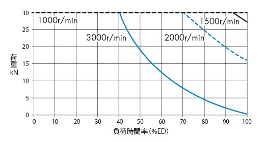
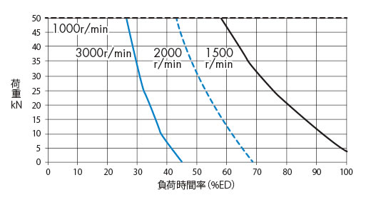
8. Check Percentage duty cycle
Check the percentage of operation time per cycle.
Check whether Percentage duty cycle %ED is within the allowable range.
Please see here for details.
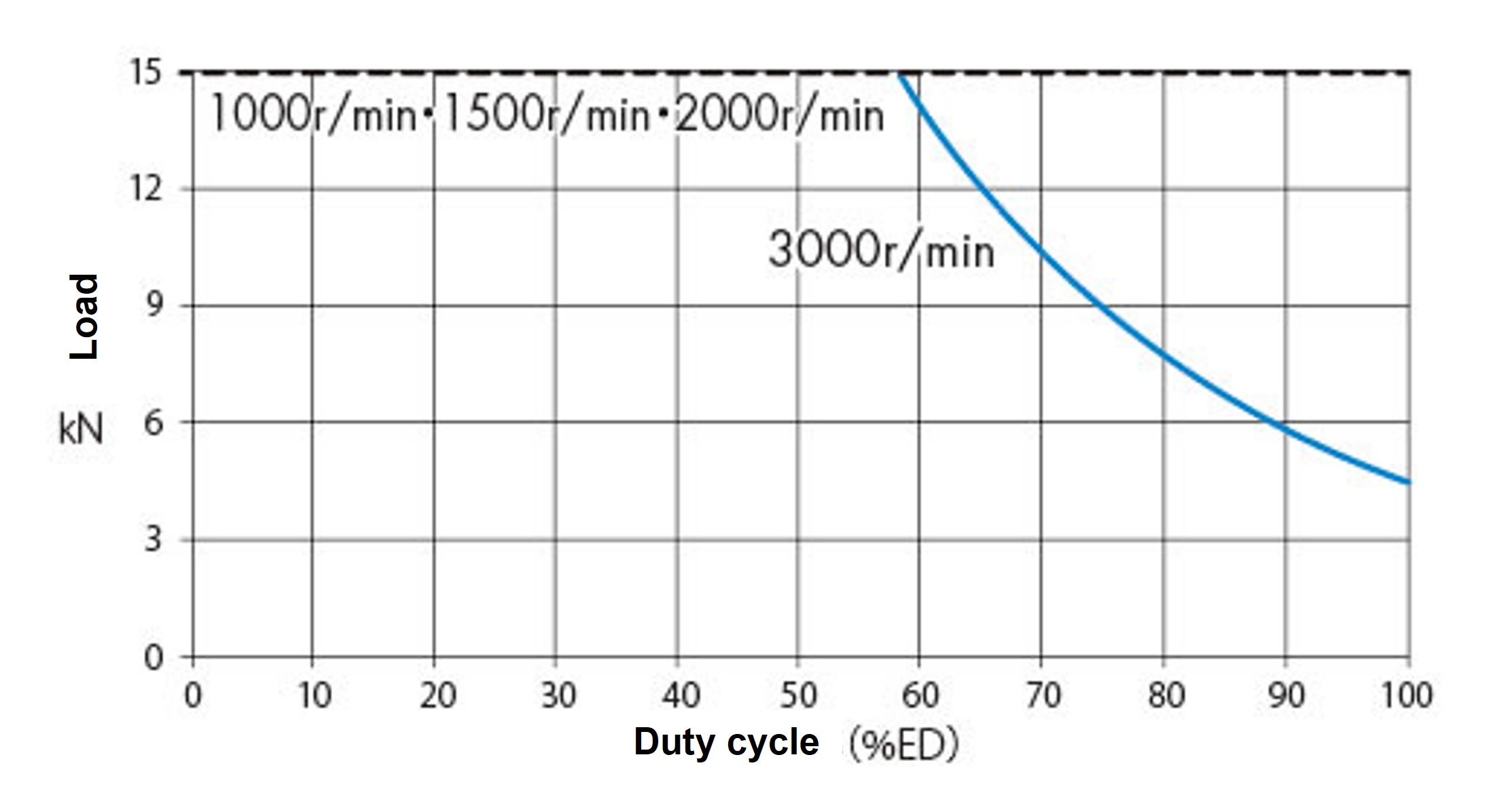
Use Linispeed Jack at a reduction gear surface temperature of 90°C or less, including the ambient temperature.
The table below shows the load factor (%ED) that will keep the reducer surface temperature below 90°C (this is not a guaranteed value).
Please check the surface temperature of the reducer during actual use.

SJ015H
Ambient temperature 20℃
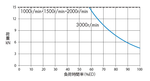
[Click to enlarge]
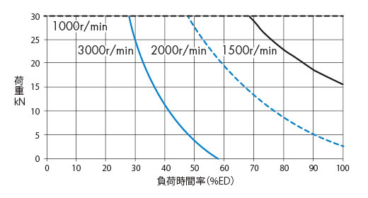
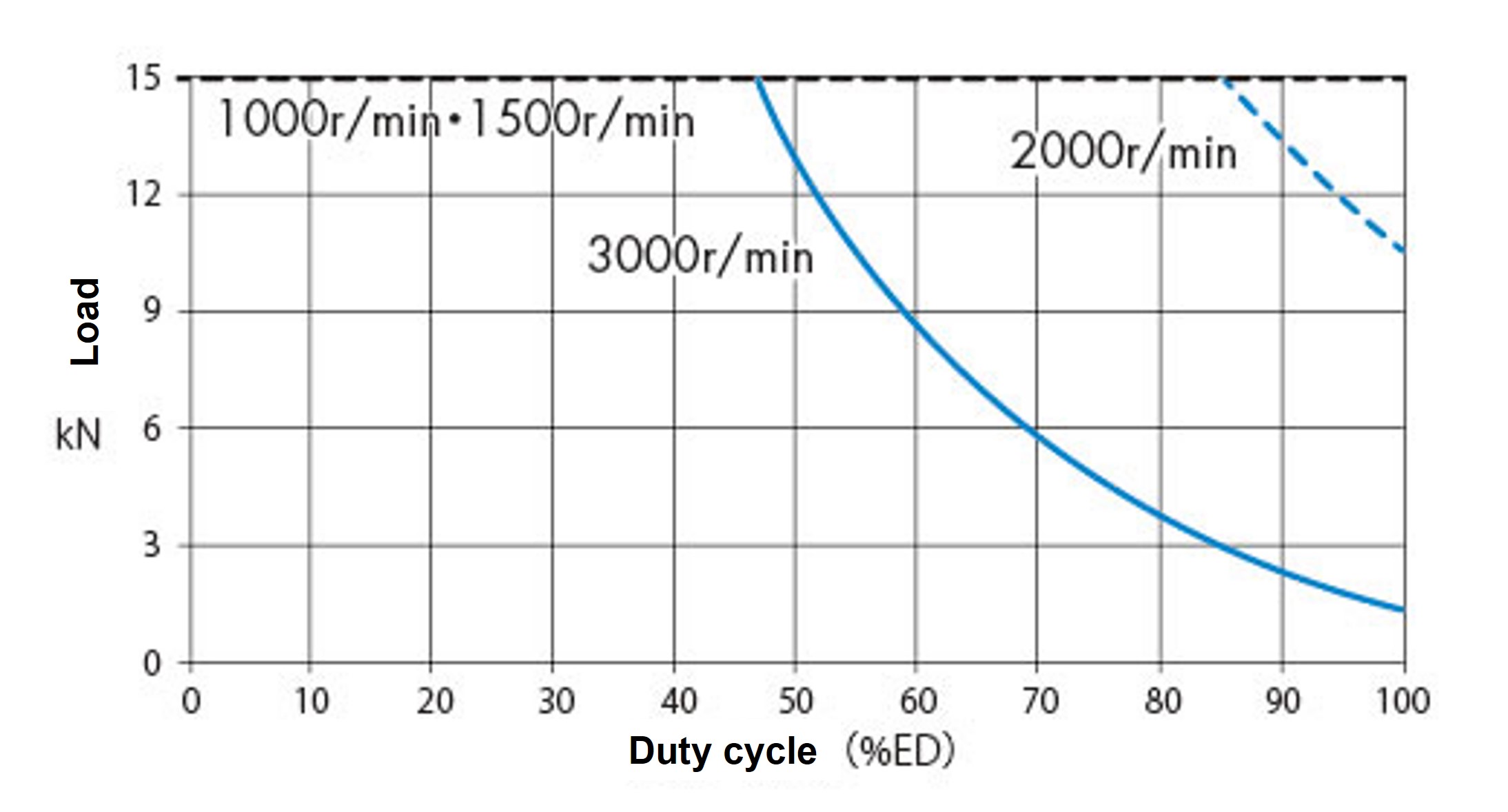
Ambient temperature 30℃
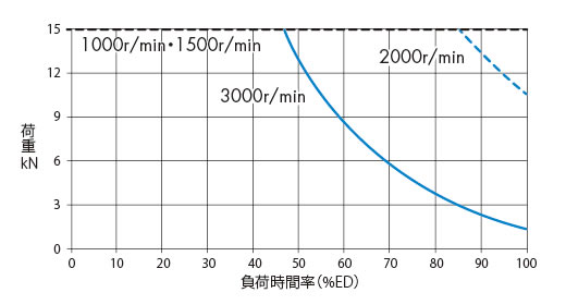
[Click to enlarge]
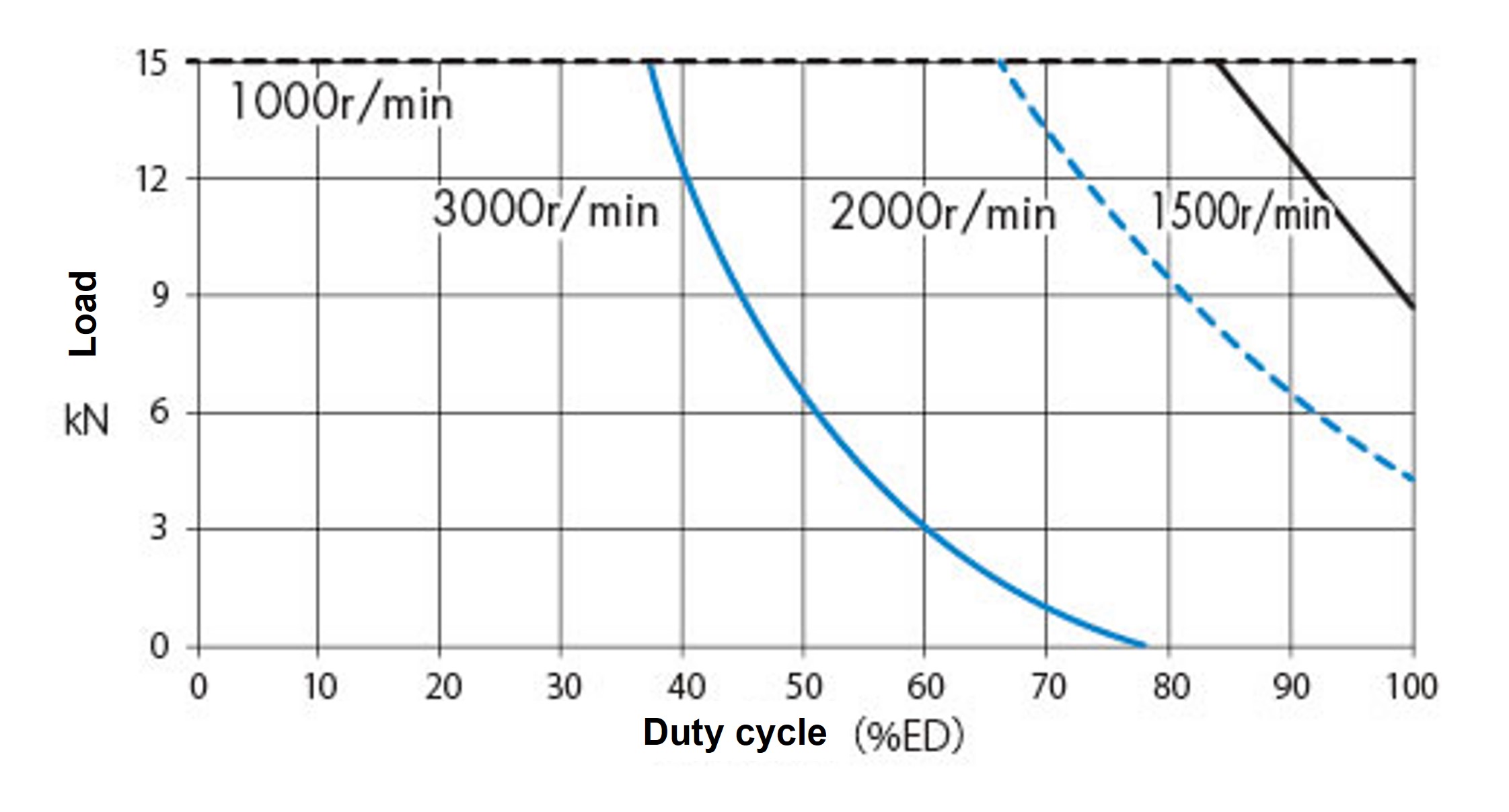
Ambient temperature 40℃
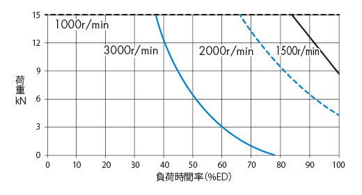
[Click to enlarge]
SJ030H
Ambient temperature 20℃
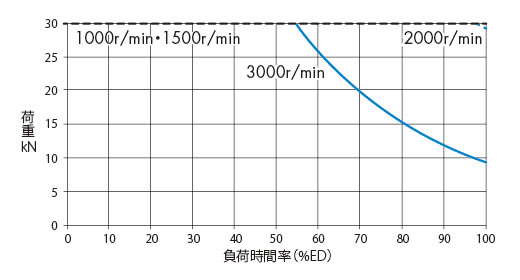
[Click to enlarge]
Ambient temperature 30℃
[Click to enlarge]
Ambient temperature 40℃
[Click to enlarge]
SJ050H
Ambient temperature 20℃
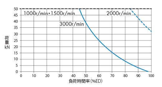
[Click to enlarge]
Ambient temperature 30℃
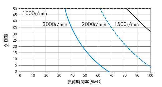
[Click to enlarge]
Ambient temperature 40℃
[Click to enlarge]
%ED = Operating time for one cycle Operating time for one cycle + Rest time for one cycle x 100 (%)
The formula to calculate Percentage duty cycle %ED from the time cycle table is as follows:
%ED = t1 + t3 t1 + t2 + t3 + t4 ×100(%)
9. Check the required input torque
Calculate the required input torque.
When using a servo motor, select a model that satisfies the servo motor's allowable torque.
T = W×ℓ 2×π×R×η + To
T: Required input torque N・m
W: Lifting load N
ℓ: Screw lead m
π: Pi 3.14
R: Worm speed ratio
η: Overall jack efficiency or starting efficiency Note)
To: No-load idling torque N・m
*For screw lead, worm speed ratio, overall efficiency, and no-load idling torque, please refer to Major Specifications page for each product. Please pay attention to the units of screw lead.
0.025m-->Example) 25mm ---> 0.025m
Note: Be sure to check the required input torque at startup using the startup efficiency.
10. Check the required input capacity
P = T×N 9550
T: Required input torque N・m
P: Required input capacity kW
N: Input rotation speed r/min
11. Check the input shaft torsional torque
The number of jacks that can be connected in the same line is limited by the shaft strength, so please refer to the allowable input shaft torque.
Example: When the jacks are arranged in a straight line as shown in the diagram below, the required input torque of two jacks is transmitted to the input shaft of the driving jack.
Check that the torque of these two units is below the allowable input shaft torque.
*Please be careful not to let the peak torque at startup exceed the allowable input shaft torque.
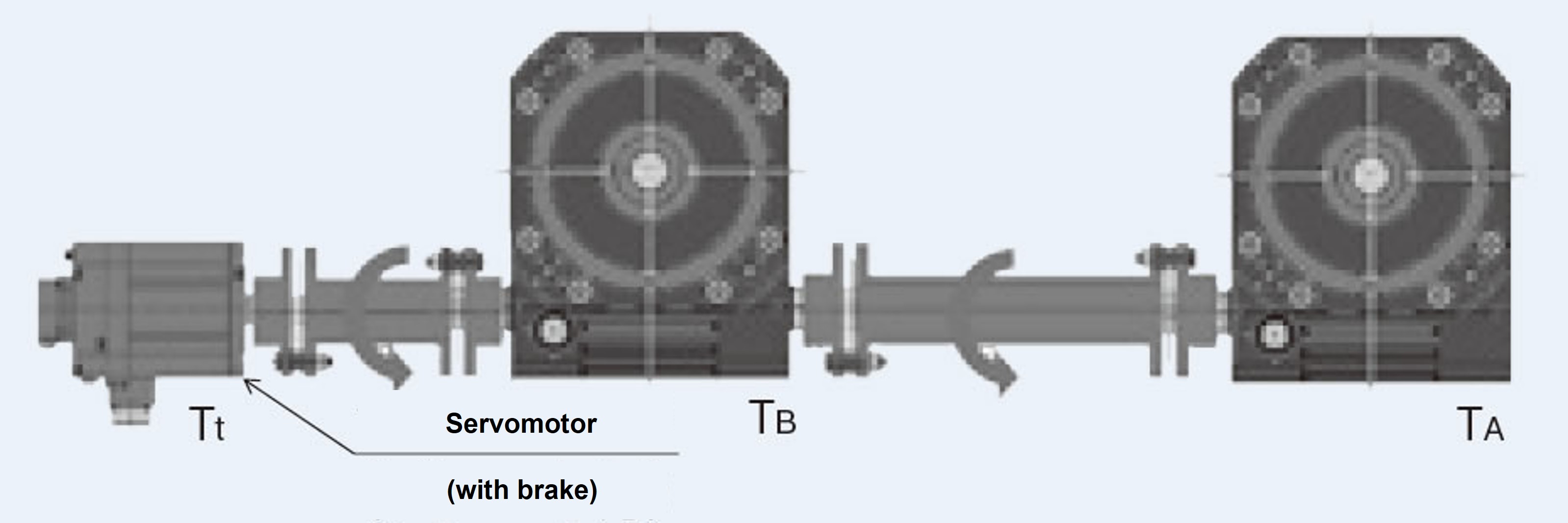
Required torque for jack A only: T A
Required torque for jack B only: T B
Required torque of driving source Tt = T A + T B < Allowable input shaft torque
For the allowable input shaft torque, please refer to Major Specifications page of each product.
12. Deciding on options
Select the option according to your usage conditions.
- Output options
- ・Control options
13. Determine Linispeed Jack body model number
Determine the official model number of Linispeed Jack body.
Selection example
Requirements
Machine used: 4 linked lifters, factory temperature (30°C), no dust
Layout: Two jacks are connected and driven by a servo motor with a brake. The two sets of jacks are used to raise and lower the lift. (Figure 1)
Operating cycle...See Figure 2
- Maximum load (W): 28kN/4
- ・Screw shaft speed (V): 180 mm/s (10.8 m/min)
- ・Stroke: 540mm
Mounting type: Flange mount, flange on case side
Installation state.....Base fixed - shaft end fixed (table type End fitting attached)
Expected lifespan: 30 cycles x 2 times/hour x 8 hours/day x 250 days/year x 3 years of use
Figure 1 Layout
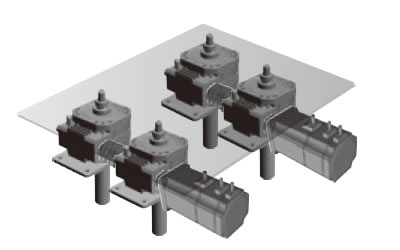
Lifting with two jacks (total of four)
Figure 2 Time cycle
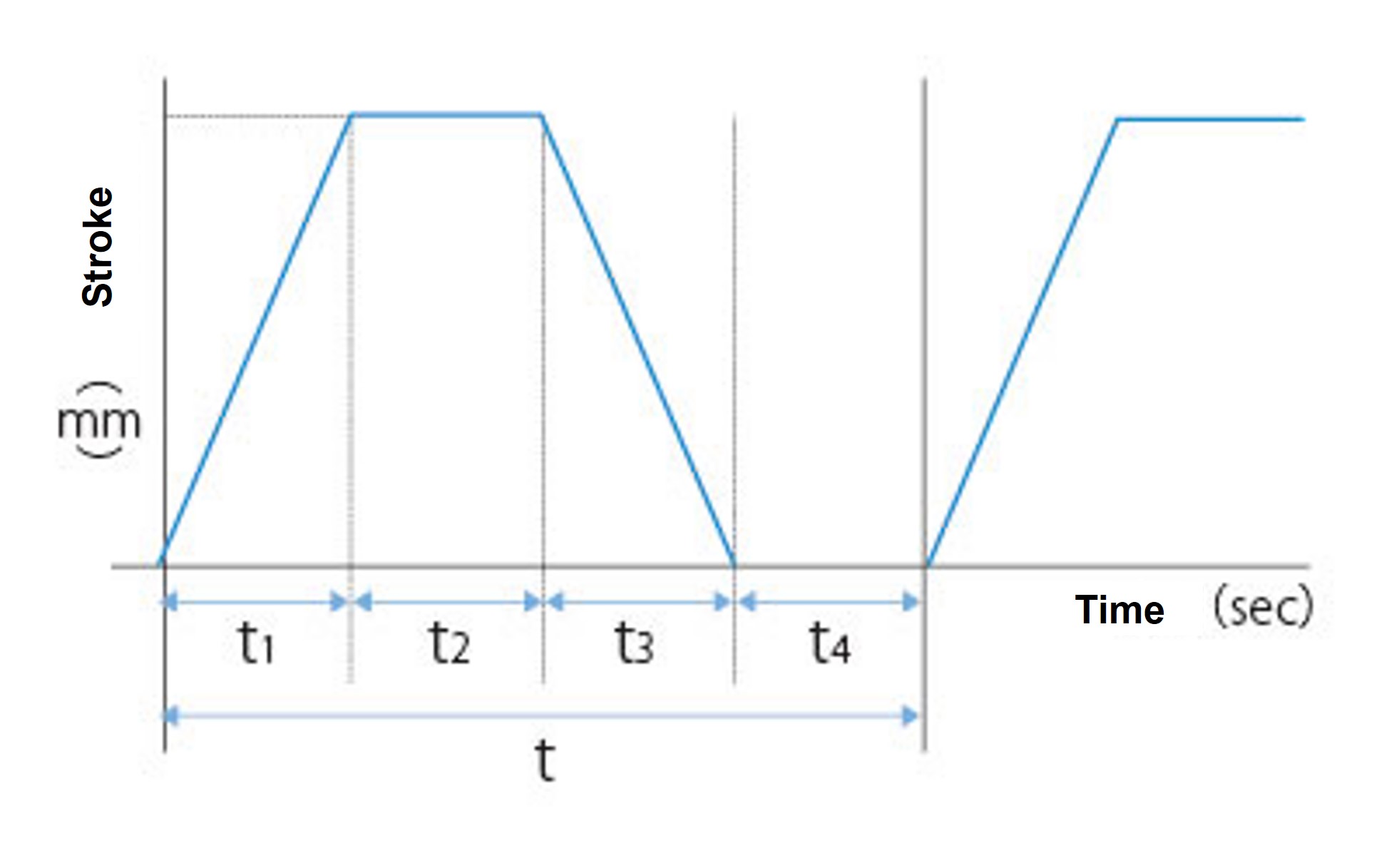
| Each time per cycle | |
|---|---|
| t1 | 3sec |
| t2 | 2sec |
| t3 | 3sec |
| t4 | 6sec |
| t | 14sec |
-
1. The corrected load Ws is calculated from the maximum load (Service factor sf = 1.3).
Ws = 28×1.3 = 36.4kN
-
2. The load W per jack is (assuming Multiple factor fd = 0.85).
W = 36.4 / 4 / 0.85 = 10.7kN
-
3. Based on the load per jack, tentatively select model SJ015H.
The stroke of the jack is set to 600mm to allow for some leeway, as the stroke used is 540mm.
-
4. Calculate the expected travel distance based on frequency of use.
Expected travel distance = 0.54 x 2 x 30 x 2 x 8 x 250 x10 -3 x 3 = 388.8km
Please refer to here for the expected lifespan of the screw shaft, and then find the jack frame number from the intersection of the expected travel distance and the load.
Since the SJ015H cannot meet the expected travel distance, the model will be SJ030H. ...OK
-
5. Because a compressive load is applied, the allowable buckling load is calculated using this buckling calculation formula. The safety factor is sf = 4.
Pcr = 20×104(30.72/775)2 = 295.8kN
sf = 295.8/10.7 > 4 ...OK
6. Consideration of input shaft overhang load is not necessary as the servo motor is directly driven with a brake.
-
7. Calculate the required input rotation speed of the jack from the required screw shaft speed.
N = 10.8 / 0.025×6 = 2592 r/min
Please pay attention to the units of screw shaft speed and screw lead.
10.8m/min、25mm --->0.025m)-->(180mm/s --->10.8m/min, 25mm --->0.025m) -
8. Check Percentage duty cycle from the time cycle table.
%ED = (3 + 3) / 14×100 = 43%ED
Check the allowable Percentage duty cycle here.
With an input speed of 2592 r/min and an ambient temperature of 30°C, the allowable Percentage duty cycle is 50%ED.
50%ED > 43%ED ...OK
×(You can move it by dragging it)Use Linispeed Jack at a reduction gear surface temperature of 90°C or less, including the ambient temperature.
The table below shows the load factor (%ED) that will keep the reducer surface temperature below 90°C (this is not a guaranteed value).
Please check the surface temperature of the reducer during actual use.
SJ015H
Ambient temperature 20℃
[Click to enlarge]
Ambient temperature 30℃
[Click to enlarge]
Ambient temperature 40℃
[Click to enlarge]
-
9. Calculate the required input shaft torque per jack.
Required input torque in steady state
T = 10.7×1000×0.025 / 2 / π / 6 / 0.87 + 6 = 14.2N・m
Please check Major Specifications page for each product for screw lead, speed ratio, overall efficiency, and no-load idling torque.
0.025m)-->For overall efficiency, please use the value for each input rotation speed. Please pay attention to the screw lead unit (25mm ---> 0.025m).
Required input shaft torque at startup
T' = 10.7×1000×0.025 / 2 / π / 6 / 0.65 + 6 = 16.9N・m
Please check Major Specifications page for each product for startup efficiency.
-
10. Since one servo motor is used to drive two jacks, calculate the required input shaft torque per servo motor with brake.
The torque required for the servo motor is
Tm = 14.2×2 = 28.4N・m
The starting torque required for the servo motor is
T'm = 16.9×2 = 33.8N・m
When selecting a servo motor, consider a model with a brake that satisfies a rated torque of 28.4 N m at a rated speed of 3000 r/min.
Also, make sure that the starting torque is sufficient.Reference) Required capacity of servo motor
P = 28.4×3000 / 9550 ≒ 9kW
-
11. Since the two jacks are connected in the same line, the input shaft of the jack closest to the drive side is subjected to the torque of both jacks.
Check that the input shaft torque of the jack is below the allowable input shaft torque specified in SJ030H.Torque for two jacks = 16.9 + 16.9 < 65N・m...OK
-
12. Jack options
テーブル形先端金具付-->Shaft end shape (End fitting) --->Table type End fitting fitting
必要に応じジャバラ(特形品)を使用ください-->Less dust ---> Use bellows (specially shaped) if necessary
-
13. Based on the above considerations, Linispeed Jack model number is determined to be SJ030H-TCT6M.

