technical data linear actuator Linispeed Jack Allowable Buckling Load
Allowable buckling load table
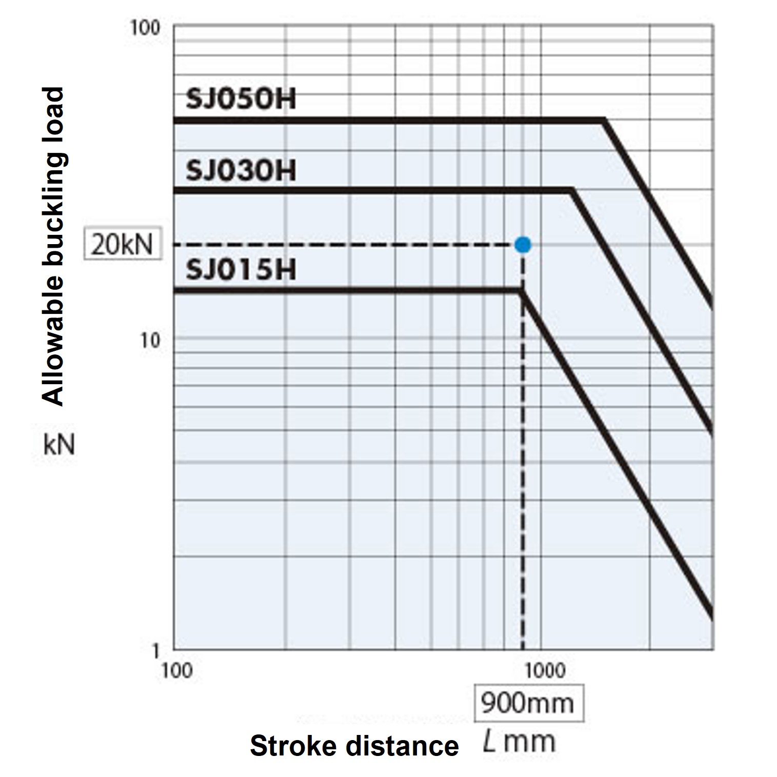
- ・When using a jack under compressive load, use this graph to determine the jack frame size for the buckling load. The buckling selection graph takes into account a buckling safety factor of SF=4.
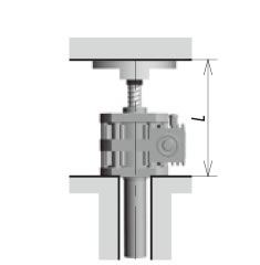
- (1) Select the distance L between the load points from the installation conditions shown in the diagram below. (Please contact us for installation conditions other than those shown in the diagram below.)
- (2) Select the jack frame number from the intersection of the load W per jack (vertical axis) and the distance between the application points (horizontal axis).
- - Avoid applying lateral loads. The buckling selection graph on the right does not take lateral loads into consideration.
- - If the device is designed so that the screw shaft is subjected to tensile load during installation, it will be economical and will not buckle.
Fixed base - shaft end support

Base fixed - shaft end fixed
- Note)
- 1. The line ---- on this graph shows an example where the load W is 20 kN and the distance between the load points is 900 mm in the above installation state.
This graph assumes a buckling safety factor of sf=4, and in this case, the SJ030H jack can be selected, which satisfies the intersection of the vertical and horizontal axes. - 2. If detailed consideration is required, please check the calculation formula below.
Distance between load points: L (distance from installation surface to load mounting surface)
| SJ015H | SJ030H | SJ050H | |
|---|---|---|---|
| Table-shaped End fitting (M) | 25mm | 33mm | 33mm |
| I-shaped End fitting (I) | 50mm | 75mm | 80mm |
| X dimension (MIN) | 187mm | 202mm | 236mm |
When using a table type or I-type End fitting, add the length of each end shape to the actual stroke.
Example: When using an I-type End fitting with a stroke of 500 mm for the SJ030H.
500 + 277 = 777mm
Note)
When attaching a customer-supplied End fitting, add the X dimension (MIN) and the length of End fitting to the actual stroke. Note that the X dimension does not include the 32 mm screw length for attaching End fitting to the screw shaft end.

Allowable buckling load calculation formula
The allowable buckling load of the jack's screw shaft can be calculated as follows:
Make sure that PCR > W × Sf.
PCR: Allowable buckling load N
d: Thread root diameter mm
m: Support coefficient (20×10 4)
L: Distance between points of action Note) mm
W: Load per jack N
Sf: Buckling safety factor (generally 4)
Fixed base - shaft end support
Base fixed - shaft end fixed
| Allowable buckling calculation example |
|---|
|
SJ030H-TUT8M (stroke 800mm) load (W) 24500N, PCR = 20×10 4 ×(30.7 2 /1035) 2 *L = 1002 + 33 = 1035mm ST800mm X dimension: 1002mm Table End fitting: 33mm From the product page |
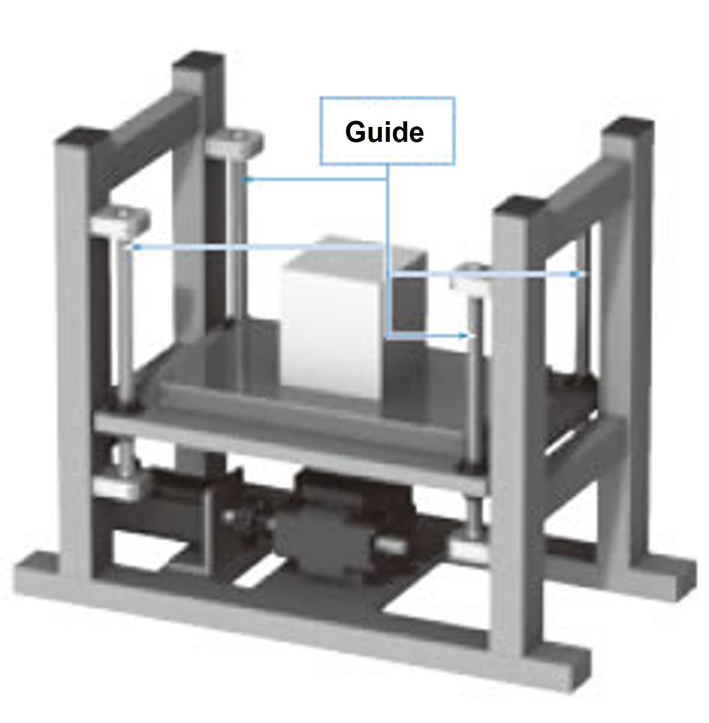
Lateral load
Linispeed Jack cannot withstand loads other than those in the axial direction.
If a lateral load is applied, please install a guide as shown in the diagram on the right to prevent the lateral load from acting directly on the jack.