technical data linear actuator Linipower Jack Selection
Requirements
Machinery used: Table lifter, stage lifting device, conveyor line switching device, etc.
Layout... Interlocking pattern (4 units, 6 units, etc.), drive, coupling, etc.
Maximum load (W)..... Mass of load or workpiece N{kgf}
Screw shaft speed (V)..... Required speed of the jack m/min
Stroke: Actual stroke used mm
Screw type: Ball screw type (JWB), High lead ball screw type (JWH), Trapezoidal Screw type (JWM)
Mounting type: Basic type (for lifting or hanging, with or without anti-rotation device), traveling nut type (for lifting or hanging)
Installation condition..... Base fixed, shaft end clevis, etc. - Buckling consideration when compressive load is applied
Expected life..... Jack service life (JWB, JWH only)
Selection Procedure
1. Calculation of the correction load Ws
Considering the nature of the load, calculate the corrected load Ws by referring to Service factor (Table 1).
Corrected load Ws (N{kgf}) = Maximum load W (N{kgf}) × Service factor Sf
Table 1. Service factor Sf
| Load Nature | Usage example | Service factor |
|---|---|---|
| Smooth operation without shock Load inertia small |
Valve opening and closing Conveyor switching device |
1.0~1.3 |
| Operation with slight impact Load inertia medium |
Various moving devices Various lifter lifting |
1.3~1.5 |
| Operation with large shocks and vibrations Large load inertia |
Transporting objects by cart, positioning and maintaining rolling rollers | 1.5~3.0 |
Note: The above Service factor are general guidelines and should be determined taking into consideration the conditions of use.
2. Calculating the load W per jack
The load W per jack is calculated from the corrected load Ws. In the case of linked operation, refer to Multiple factor (Table 2) for calculation.
Load per jack W (N{kgf}) = Corrected load Ws (N{kgf}) Number of jacks used × Multiple factor fd
Table 2. Multiple factor fd
| Number of linked units (units) | 2 | 3 | 4 | 5~8 |
|---|---|---|---|---|
| Multiple factor | 0.95 | 0.9 | 0.85 | 0.8 |
3. Tentatively select the model number of Linipower Jack
Refer to the "Points to consider when tentatively selecting" to tentatively select the model number of the jack.
Points to consider when tentatively selecting a product
- 1. The worm speed ratio is tentatively selected based on the screw shaft speed. If it is difficult to determine, consider speed ratio H.
- 2. Select the stroke with a margin of safety in mind.
- 3. Select options as needed.
4. Checking buckling and screw shaft rotation speed
- 1. Consideration of allowable buckling load
If a compressive load is applied, make sure that it is below the allowable buckling load. (Here reference)
If the allowable value is exceeded, increase the size of the jack and recalculate. - 2. Allowable screw shaft rotation speed
In the case of a traveling nut specification, check that the screw shaft rotation speed is below the allowable speed. (Here reference)
If the allowable value is exceeded, increase the size of the jack and recalculate.
5. Check the required input rotation speed
The required input rotation speed of the jack is calculated from the required screw shaft speed.
N = V ℓ ×R
N: Input rotation speed r/min
V: Screw shaft speed m/min
ℓ: Screw lead m
R: Worm speed ratio
6. Check the required input torque
Calculate the required input torque.
T = W×ℓ 2×π×R×η + To
T: Required input torque N・m{kgf・m}
W: Lifting load N{kgf}
ℓ: Screw lead m
π: Pi 3.14
R: Worm speed ratio
η: Overall jack efficiency
To: No-load idling torque N・m{kgf・m}
- Note)
Please refer to Major Specifications page for each product for screw lead, worm speed ratio, overall efficiency, and no-load idling torque.
Please pay attention to the units of screw lead. Example) 8mm → 0.008m
7. Check the required input capacity
SI units P = T×N 9550
Gravity unit P = T×N 974
T: Required input torque N・m{kgf・m}
P: Required input capacity kW
N: Input rotation speed r/min
8. Consideration of allowable overhang load
When installing a sprocket, gear, belt, etc. on the input shaft, check that it is below the allowable overhang load (see here).
If it exceeds the allowable value, increase the size of the jack and recalculate.
9. Checking the lifespan (JWB and JWH types only)
Check whether the expected life span is met (see here).
If you want to increase the expected travel distance, increase the jack size and recalculate.
*Lifespan calculations cannot be performed for JWM (Trapezoidal Screw) types.
10. Deciding on options
Select the option according to your usage conditions.
- ・Output options ・Mounting options
- ・Control options ・Input options
- ・Included options
(See Drawing Library for each product)
11. Deciding the jack body model number
The official model number of Linipower Jack body will be determined.
Selection of peripheral devices
Motor Selection
Calculate the required capacity Pt of the drive source for interlocking and select the drive source
1. Calculating the total required torque Tt of the drive source
Calculate the required torque T1 to T4 on the drive source side for each jack, and add them together to calculate the total required torque Tt for the drive source.
[Required torque per jack]
T 1 to 4 = T (gearbox efficiency) Number of gearboxes
[Total required torque of drive source]
Tt = T1 + T2 + T3 + T4
T 1 to 4: Required torque on the drive source side of each jack N・m{kgf・m}
T: Required input torque of the jack body N・m{kgf・m}
Gearbox efficiency: Generally taken as 0.9.
Tt: Total required torque of the drive source N・m{kgf・m}
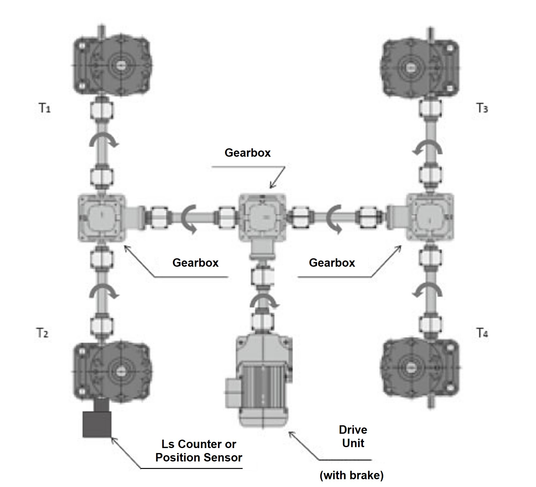
When four units are connected (Figure 1), T 1 to 4 = T0.9 2.
Figure 1
2. Check the allowable input shaft torque
Check that the required input torque of the jack is equal to or less than the allowable input torque of the selected jack.
example)
When the jacks are arranged in a straight line as shown in Figure 2, the required input torque of two jacks is transmitted to the input shaft of the jack on the drive side.
Check that the torque of these two units is below the allowable input shaft torque.
Figure 2
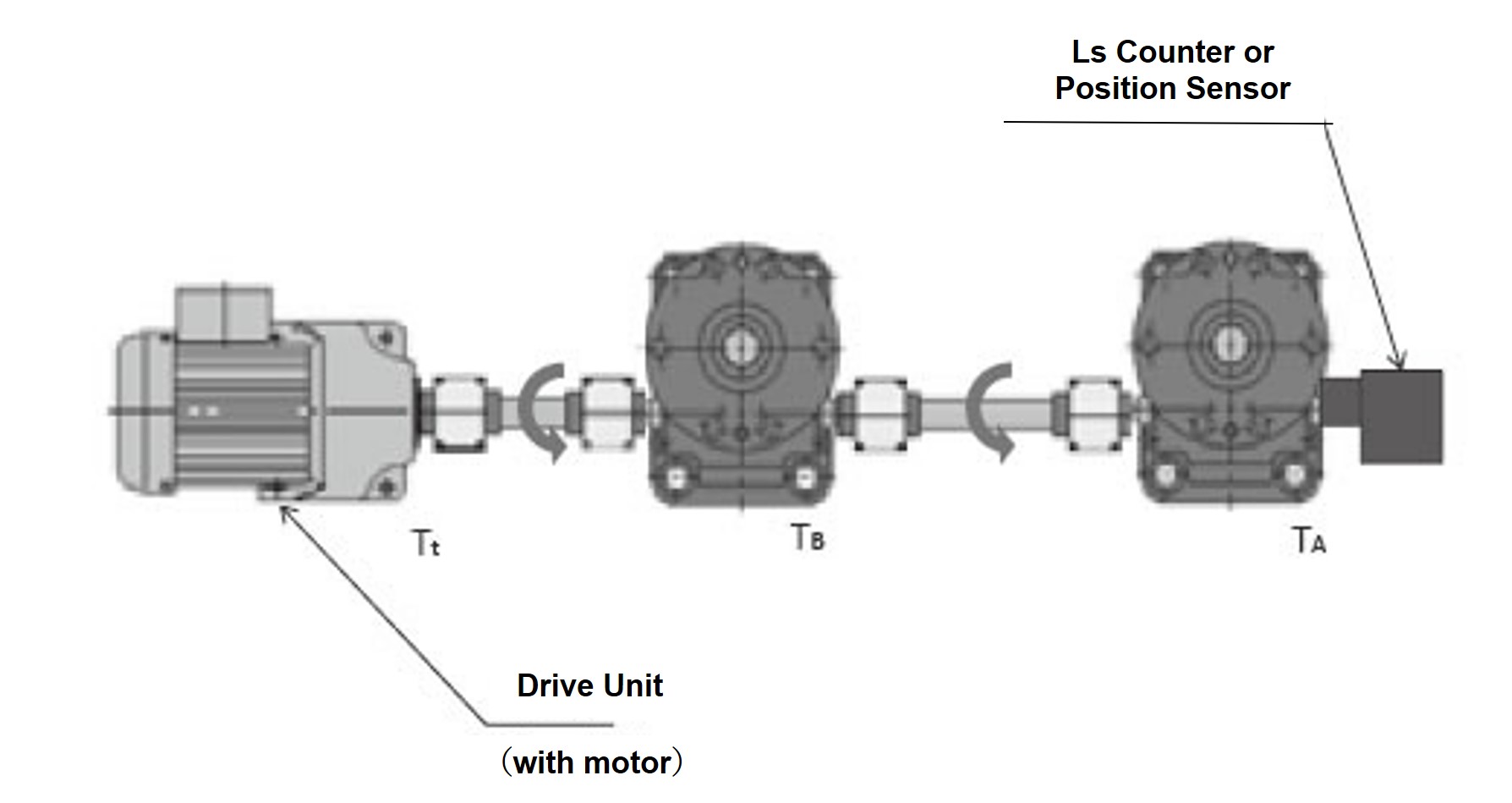
Required torque for jack A only: T A
Required torque for jack B only: T B
Required torque of driving source T t = T A + T B < Allowable input shaft torque
3. Calculation of the required drive source capacity Pt
The required drive capacity Pt is calculated from the input rotation speed N and the total required torque Tt calculated in 1.
SI units Pt = Tt × N 9550
Gravity unit Pt = Tt×N 974
Pt: Required drive capacity kW
Tt: Total required torque of the drive source N・m{kgf・m}
N: Jack input rotation speed r/min
Selection of other equipment
Gearbox
Select based on input rotation speed and allowable torque.
Please refer to the separate catalog for Tsubaki Miter Gear Box.
Coupling
Select based on the allowable torque and maximum shaft diameter.
Please refer to the Tsubaki Coupling catalog.
Linipower Jack selection example
example:
4-unit linked lifter (layout is the same as the 4-unit linked pattern in the diagram below) Factory temperature is normal, there is some dust
The guide is installed on the lifter device side to prevent lateral loads, and the base is fixed - shaft end is supported/fixed. The power supply is three-phase 220V/60Hz.
Frequency of use: 2 times/hour x 8 hours/day x 300 days/year x 3 years of use
- (1) Maximum load: 98.0kN{10tf}/4 units
- (2) Required speed: 5mm/s (0.3m/min)
- (3) Stroke: 260mm
4-unit linked pattern
*See above for T1 to T4
| SI units |
|---|
|
| {gravity unit} |
|---|
|
Peripheral device selection example
A. Determining the driving source
1. Required torque T1 (2.3.4) on the drive side of each jack
The dispersion path for all four jacks is the same.
SI units Tt = T 1 × 4 = 83.5 N m
Gravity unit Tt = T 1 ×4 = 8.52kgf・m
2. Consideration of the maximum allowable input shaft torque of the jack
In this linked pattern, there are no more than two jacks lined up in series, so there is no need to consider this.
3. Required drive capacity Pt
Also, the input speed is 180 r/min.
1800 180 = 10Based on the above, we select the 2.2kW Tsubaki GMTR221-42L10B Gear Motor with brake.
For details, please refer to the Tsubaki small gear motor catalog.
B.1. The gearbox has an input speed of 180 r/min.
The required input torque for the jack is 15.4N・m {1.57kgf・m }
1-1. The gearboxes on the left and right sides of the jack have the torque of two jacks.
20.9×2
0.9
= 46.4N・m
2.13×2
0.9
= 5.11kgf・m
We selected the ED4M gearbox, which meets the above requirements.
(However, please be careful of the direction of rotation of the gearbox.)
1-2. The gearbox on Gear Motor side is for four jacks, so the torque
20.9×4
0.9 2
= 103N・m
2.13×4
0.9 2
= 8.69kgf・m
The gearbox ED6M that clears this requirement is selected.
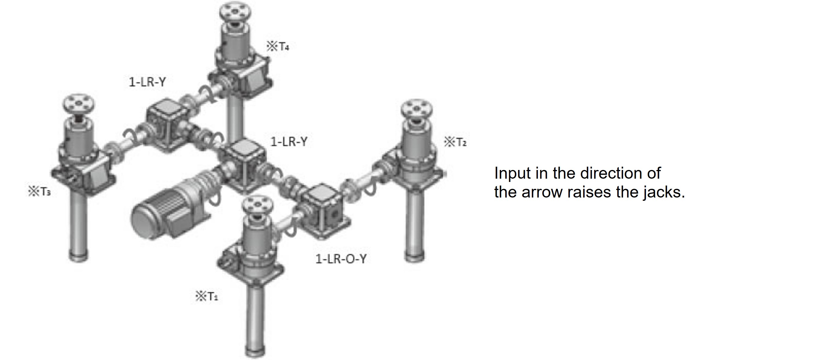
Jack side gear box
- Left side: ED4M 1-LR-OY
- Right side: ED4M 1-LR-Y
Gear Motor side gearbox
- ED6M 1-LR-Y
(For details, please refer to the Tsubaki Miter Gear Box Catalog)
B.2. Please select various couplings according to the equipment conditions.
(For details, please refer to the Tsubaki Coupling Catalog)
The method of consideration is
2-1 For the jack-to-gearbox connection, please select the required jack input torque of 16.9 N・m {1.73 kg・fm}, jack input shaft diameter (Φ20 for JWB050USH), and gearbox shaft diameter (Φ19 for ED4M).
The required number is 2 x 2 x 2 = 8 pieces.
Between the 2-2 gearboxes, the torque is equivalent to two jacks.
20.9×2 0.9 = 50.1N・m 2.13×2 0.9 = 5.11kgf・mPlease also select from the jack side gearbox shaft diameter (Φ19 for ED4M) and Gear Motor side gearbox shaft diameter (Φ25 for ED6M).
The required number is 2 x 2 = 4.
Between the 2-3 gearbox and Gear Motor, the torque is equivalent to that of four jacks.
20.9×4 0.92 = 85.2N・m 2.13×4 0.92 = 8.69kgf・mPlease also select from the gearbox shaft diameter (Φ25 for ED6M) and Gear Motor output shaft diameter (Φ42 for GMTR221-42L10B). Two pieces are required.

