technical data linear actuator Linipower Jack technical data
Allowable buckling load calculation formula
The allowable buckling load of the jack's screw shaft is calculated using the formula below.
Make sure that P CR > W×Sf.
P CR: Allowable buckling load N{kgf}
d: Thread root diameter mm (Please refer to Major Specifications page for each product.)
m: Support coefficient (Select the installation condition from the diagram below.)
L: Distance between points of action mm
(Maximum dimensions in the dimension table for each frame number. If End fitting is required, please refer to End fitting dimensions.)
W: Load per jack N{kgf}
Sf: Buckling safety factor (generally 4)
Installation status
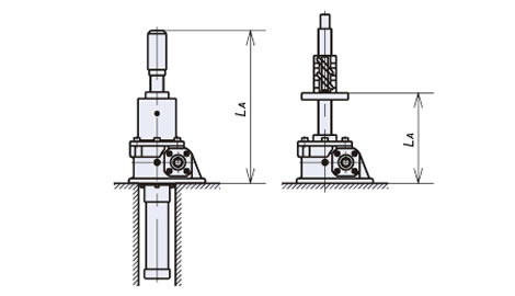
A Fixed base, free shaft end
| m | |
|---|---|
| SI units | 2.5×10⁴ |
| Gravity Units | {2.5×10³} |
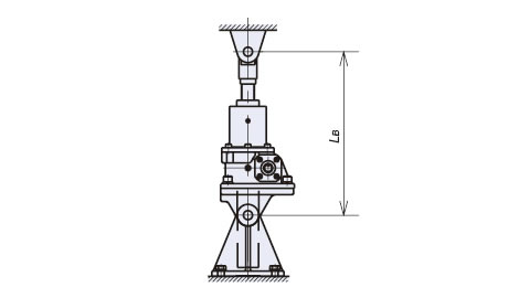
B Clevis support on both ends
| m | |
|---|---|
| SI units | 10×104 |
| Gravity Units | {10×103} |
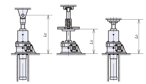
C Fixed base, single shaft end support/fixed
| m | |
|---|---|
| SI units | 20×104 |
| Gravity Units | {20×103} |
| SI units |
|---|
|
When calculating PCR when using JWM100USH5JI with a load of 49,000N and installation condition C (base fixed - shaft end supported/fixed),
|
| {gravity unit} |
|---|
|
When calculating PCR when using JWM100USH5JI with a load of 5000 kgf and installation condition C (base fixed - shaft end supported/fixed),
|

