technical data linear actuator Linipower Jack technical data
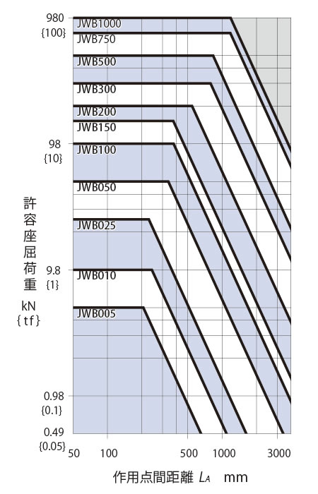
Allowable buckling load
- - When using with a compressive load, use this graph to determine the jack frame number for the buckling load.
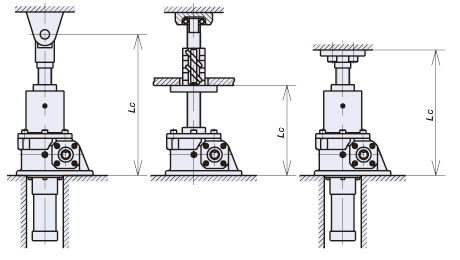
The buckling selection graph is a graph that takes into account a buckling safety factor of Sf=4.- (1) Select the distances between the load points LA and LC from the installation conditions A and C in the diagram below.
(For installation conditions other than those shown in the diagram below, please refer here.) - (2) Select the jack frame number from the intersection of the load W per jack (vertical axis) and the distance between the application points (horizontal axis).
- (1) Select the distances between the load points LA and LC from the installation conditions A and C in the diagram below.
- - Avoid applying lateral load.
The buckling selection graph below does not take into account lateral loads. - - In terms of installation, if you devise a structure in which the screw shaft is subjected to a tensile load, there will be no buckling and it will be economical.
A Fixed base, free shaft end
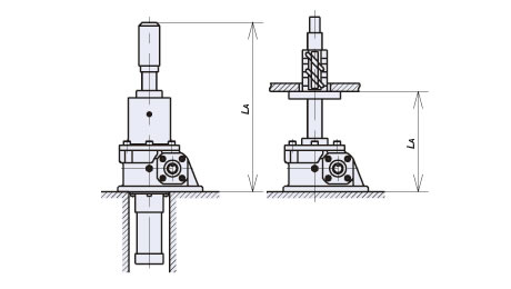
C Fixed base, single shaft end support/fixed
| Distance between points of action L A mm | Distance between points of action L C mm | |
|---|---|---|
| J.W.B. (Ball screw type) |
 [Click to enlarge] |
 [Click to enlarge] |
| J.W.H. (High lead ball screw type) |
- | 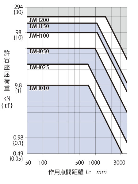 [Click to enlarge] |
| J.W.M. (Trapezoidal Screw type) |
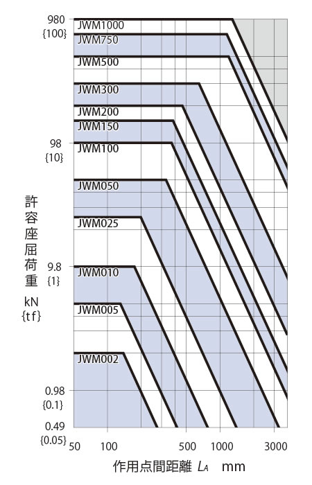 [Click to enlarge] |
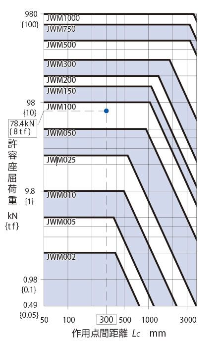 [Click to enlarge] |
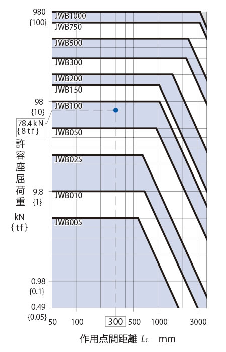
- Note)
- 1. The line ---- on this graph shows an example where the load is W78.4kN{8tf} (buckling safety factor Sf=4) and the distance between the load points is 300mm in installation condition C.
In this case, you can select the jack JWB100/JWM100, which satisfies the intersection of the vertical and horizontal axes. - 2. If detailed consideration is required, please check the calculations (here).

