technical data High-speed lifter Zip Chain Lifter Stroke Control
Stroke Control
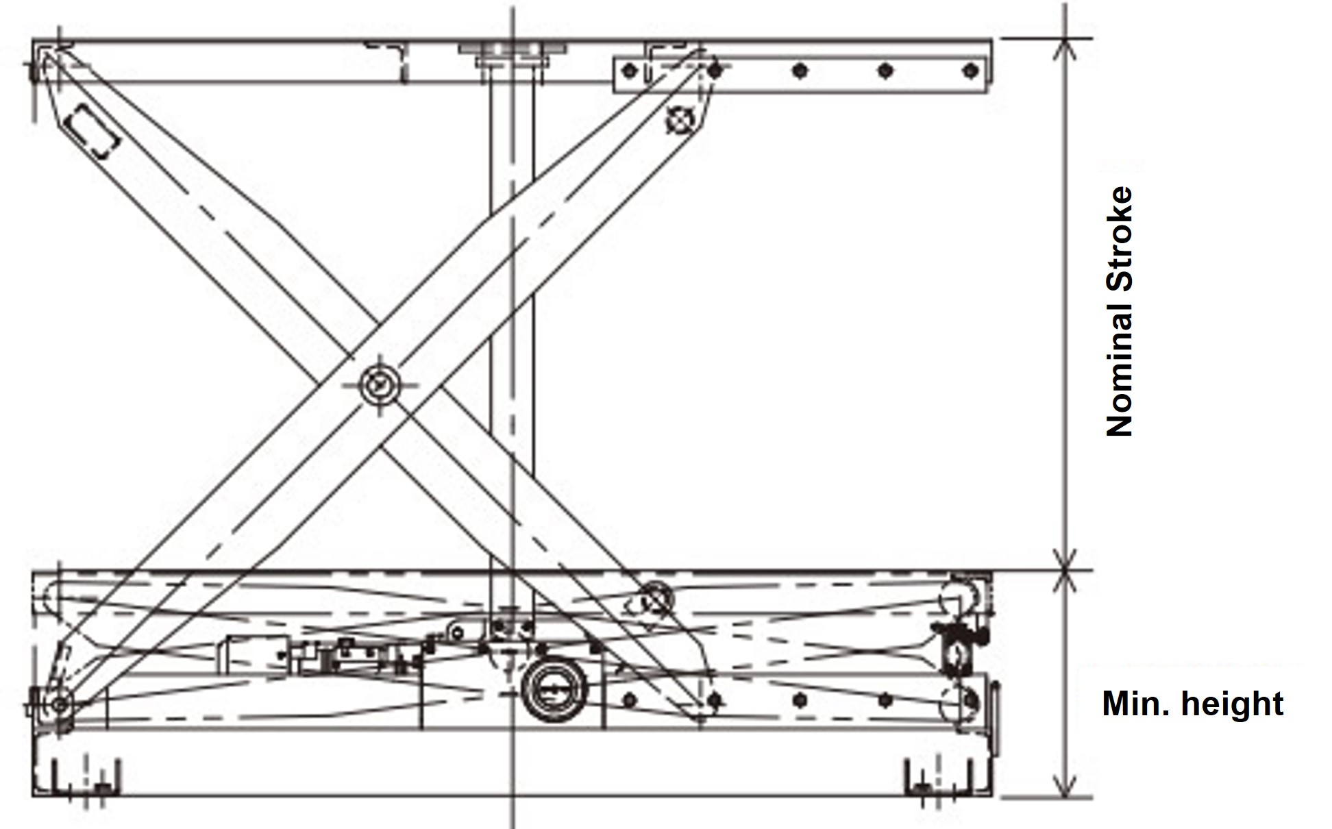
Use the lifter within its "stroke".
(Stroke ≧ Used stroke)
Position detection sensor specifications (ZSL1000)
| Stroke adjustment limit switch | |
|---|---|
| Manufacturer | Omron Corporation |
| Limit switch type | WLCA12-2-N (OMRON) equivalent product |
| Electrical capacity | AC250V 10A (cosΦ=0.4) DC5V 1mA (minimum applicable load) |
| Circuit configuration | 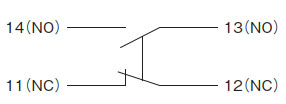 |
| Connector (compatible cable outer diameter) | SCS-10B (Φ8.5 to Φ10.5) PF1/2 |
Position detection sensor specifications (ZSL0050)
| Lower deceleration/lower limit stop | |||
|---|---|---|---|
| Manufacturer | Omron Corporation | ||
| Photomicrosensor | EE-SPX303N | ||
| Input/Output Stage Circuit Diagram |
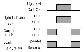
Dark ON | time chart |
 |
| Output Circuit | 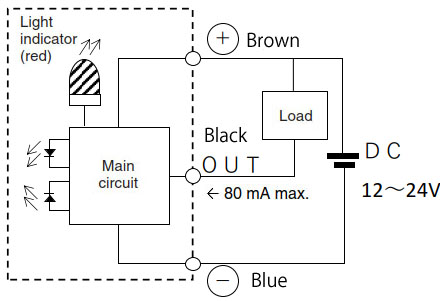 |
||
| Power Supply/Voltage | DC12-24V±10% ripple (pp) 5% or less | ||
| Connection Method | EE-1010 with 2M | ||
| Upper deceleration/upper limit stop | ||||
|---|---|---|---|---|
| Manufacturer | Omron Corporation | |||
| Photomicrosensor | EE-SX672-WR | |||
| Input/Output Stage Circuit Diagram |
time chart |
Light ON | 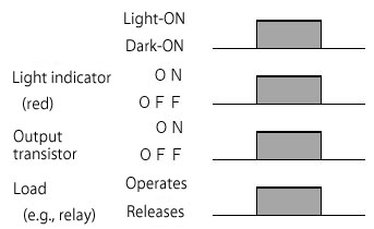 |
Connection terminals |
 |
||||
| Dark ON |
Recommendation 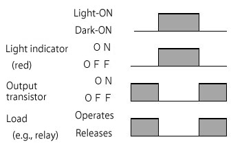 |
Connection terminals | ||
 |
||||
| Output Circuit | 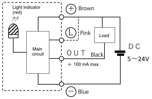 |
|||
| Power Supply/Voltage | DC5-24V±10% Ripple (pp) 10% or less | |||
| Connection Method | Cord pull-out type | |||
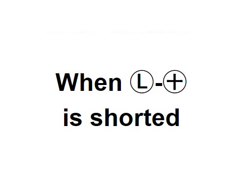
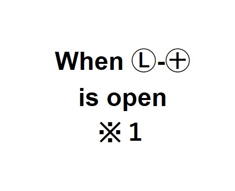
*1 Do not short-circuit the L terminal to 0V when the light is off and the ON state is set.
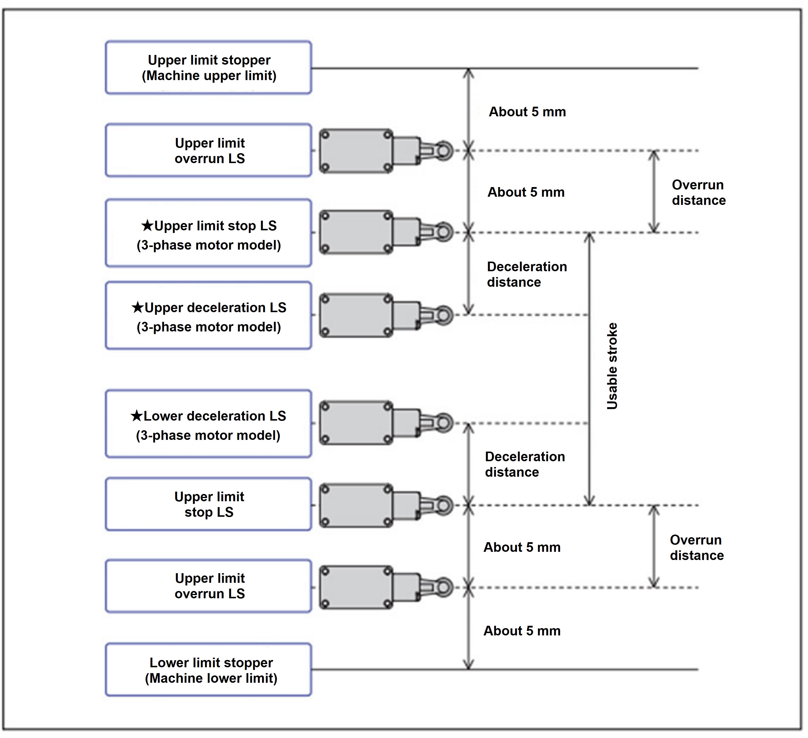
Limit switch (LS) placement (ZSL1000)

Limit switch (LS) placement (ZSL0050)
| Upper limit overrun and Lower limit overrun | Stroke adjustment limit switch | |
|---|---|---|
| Manufacturer | Omron Corporation | |
| Small Switch | D2VW-5L1-1M | |
| Contact Specifications |  |
|
| Rated voltage | AC250V | Resistive load: 5A |
| AC125V | Resistive load: 5A | |
| DC30V | Resistive load: 5A | |
The sensors marked with ★ in the limit switch layout diagram are only available with a three-phase motor. (There is no sensor in this position with a servo motor or motor with an encoder.) For details, please refer to the delivery drawing.
- The upper and lower stroke limits are set by the upper and lower limit stop switches (LS). In case the upper and lower limit stop switches do not function effectively, upper and Lower limit overrun switches are provided.
- - If the upper/lower Lower limit overrun sensor is activated, install an external brake circuit with DC external wiring and sequence circuit so that the lifter can be stopped by sudden braking. (If the lifter is raised or lowered at a speed faster than the maximum speed or the brake is switched to AC, the lifter will collide with the stopper, so this must be avoided. [This will cause a delay when braking, increasing the braking distance.]
Additionally, the upper and lower limit stoppers are set as mechanical upper and lower limits. Never touch them. If they are loose or stopped halfway, the top plate frame may come into contact with them when lowering, which could result in damage to the equipment or a serious accident. - *If intermediate stops are required during lifter operation, please use a model with a rotary encoder or servo motor.

