technical data Power-Lock Selection and Procedure
If you would like to see the selection procedures and important points, please proceed below.
If you would like to narrow down or tentatively select a product series,
Please click here.
If your usage conditions have been decided and you would like a detailed selection,
Please click here.
ML Series Selection
1. Check the maximum torque and thrust load
The maximum torque and thrust load are calculated by Service factor in the transmission capacity.
*When connecting a servo motor or stepping motor, use the maximum torque (peak torque) of each as the maximum generated torque (Tmax).
| SI units |
|---|
|
Tmax = 9550 × H n ・f Tmax = Maximum torque (N・m)
|
| Gravity Units |
|---|
|
Tmax = 974 × H n ・f Tmax = Maximum torque (kgf・m)
|
Pmax = Pax・f
- Pmax: Maximum thrust load kN{kgf}
- Pax: Thrust load kN{kgf}
- f: Service factor
f: Service factor
| Load Condition | Service factor | |
|---|---|---|
| Smooth load without shock | Small inertia | 1.5~2.5 |
| Light shock load | Medium inertia | 2.0~4.0 |
| High impact loads | Large inertia | 3.0~5.0 |
When only torque is applied
Compare the Tmax obtained above with the catalog transmission torque Mt.
Mt ≧ Tmax → Can be used.
Mt < Tmax → Consider increasing the model number or using multiple units.
When torque and thrust load are applied simultaneously
The combined load M R is calculated and compared with the transmitted torque M t.
MR = Tmax2 + (Pmax × d 2 )2
- Tmax: Maximum torque N・m{kgf・m}
- Pmax: Maximum thrust load N{kgf}
- d: shaft diameter m
Compare the M R calculated above with the catalog transmission torque Mt.
M t ≧ M R → Can be used.
M t < M R → Consider increasing the model number or using multiple units.
*This series can be used with multiple units. When using multiple units, multiply Mt by the multiplier shown in the table below to determine the transmission torque.
| Number used | 1 | 2 | 3 | 4 |
|---|---|---|---|---|
| Magnification | 1 | 1.2 | Not possible | Not possible |
2. Consideration of the axis and boss
(1) Consideration of material strength
The shaft and boss should be made of a material with a strength that satisfies the following formula.
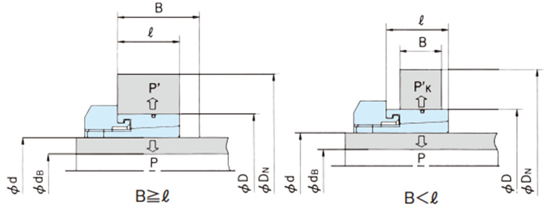
σ0.2S ≧ 1.4 × P
σ0.2B ≧ 1.4 × P' (when B ≧ ℓ)
σ0.2B ≧ 1.4 × P' K (when B < ℓ)
When B < ℓ, calculate the surface pressure P' K using the following formula.
P'K = P'・ ℓ B
- P: Shaft side pressure MPa{kgf/mm2}
- P', P'k: Boss side pressure MPa{kgf/mm 2}
- σ 0.2S: Yield stress of shaft material used MPa{kgf/mm2}
- σ 0.2B: Yield stress of the boss material used MPa {kgf/mm2}
Please refer to the steel material strength table, which shows the yield point values of representative steel materials.
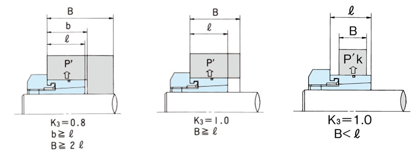
(2) Consideration of outer hub diameter
Once you have determined the Power-Lock size, boss material, and boss side pressure, find the minimum required outer hub diameter D N from the ML series Major Specifications page.
D N ≦ Boss diameter design value
If calculating, use the following formula to find the value of D N.
D N ≧ D σ0.2B + K 3 ・P' σ0.2B- K 3 ・P' (when B ≧ ℓ)
DN ≧ D σ0.2B + K3 ・P' K σ0.2B- K3・P' K (when B < ℓ)
- D N: Outer hub diameter mm
- D: Hub diameter mm
- σ 0.2B: Yield point of boss material MPa stress {kgf/mm 2}
- P', P' K: boss side pressure MPa {kgf/mm 2}
- K3: Coefficient based on boss shape (see the diagram below)
(3) Consideration of the inner diameter of the hollow shaft
When using a hollow shaft, calculate the hollow shaft inner diameter using the following formula.
dB ≦ d σ0.2S - 2 × P σ0.2S
- d B: Maximum allowable hollow shaft inner diameter mm
- d: shaft diameter mm
- σ0.2S: Yield point of shaft material MPa{kgf/mm 2}
- P: Shaft side pressure MPa{kgf/mm 2}
3. Radial load
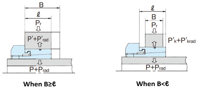
When a large load acts on Power-Lock ML as a radial load Pr, such as in a belt drive, calculate the surface pressures Prad and P'rad (P'krad) on the shaft and hub sides caused by the radial load Pr using the following formula. It is acceptable if Prad and P'rad (P'krad) are 25% or less of P and P', respectively.
Prad = 1.3 × Pr d × ℓ ≦ 1 4 × P
P'rad = 1.3 × Pr D × ℓ ≦ 1 4 × P' (when B ≧ L 1)
P'krad = 1.3 × Pr D × ℓ ≦ 1 4 × P'k (when B < L 1)
- Pr: Radial load N{kgf}
- ℓ: Contact surface width between boss and outer ring mm
- B: Boss width mm
- d: shaft diameter mm
- D: hub diameter mm
- P: Shaft side pressure MPa{kgf/mm 2}
- P', P'k: Boss side pressure MPa{kgf/mm 2}
To calculate required hub outer diameter or the required inner diameter dB of the hollow shaft when such a radial load is applied, add Prad and P'rad to P and P' (P'k) respectively.

