technical data Reducer Worm Reducer Motor Specifications
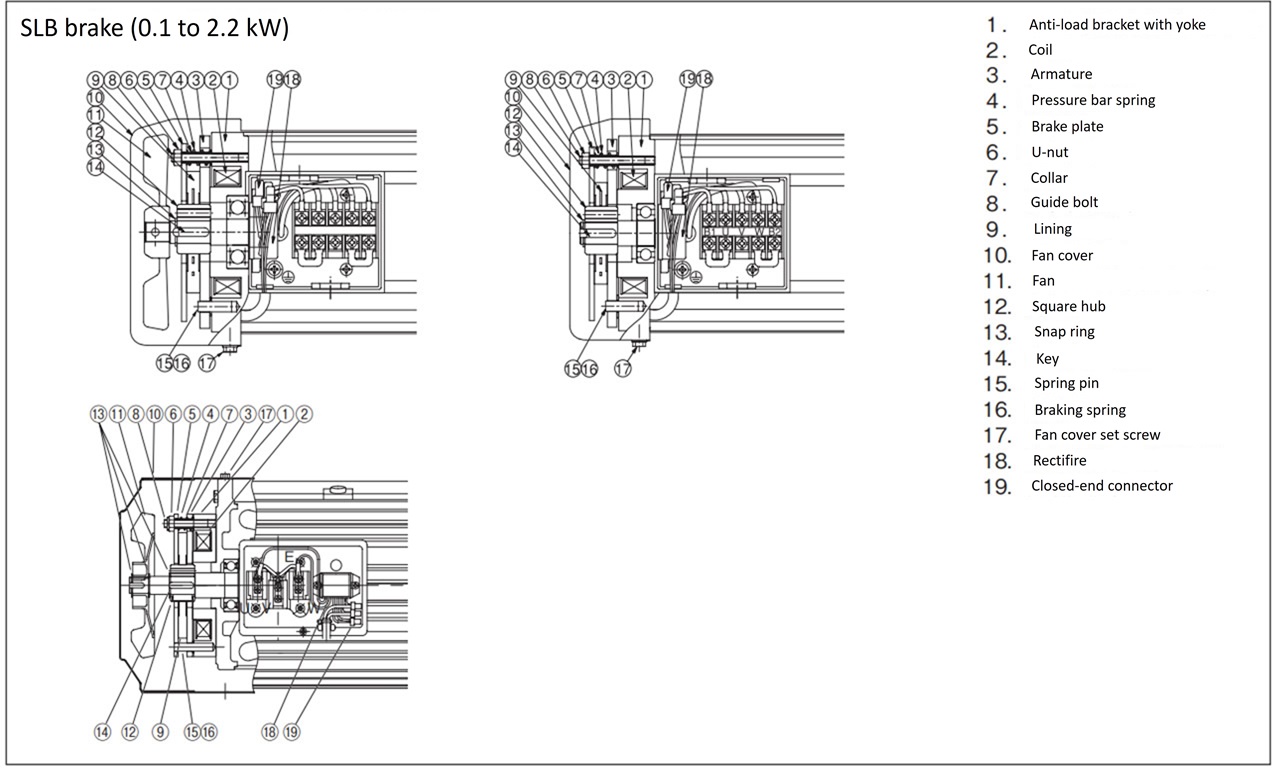
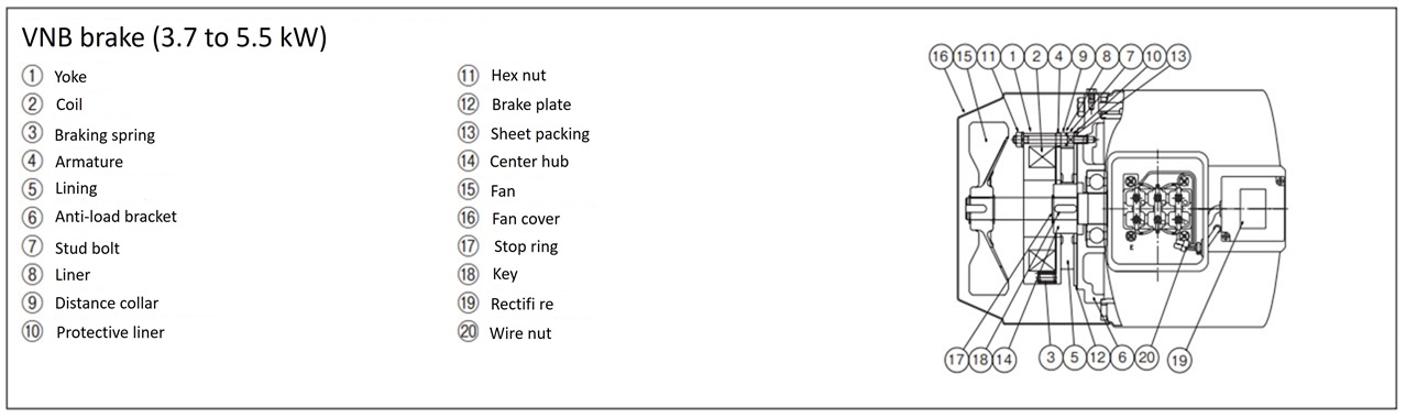
brake
1. Braking characteristics
| Motor Output | Three-phase | 0.1kW | 0.2kW | 0.4kW | 0.75kW | 1.5kW | 2.2kW | 3.7kW | 5.5kW |
|---|---|---|---|---|---|---|---|---|---|
| Brake model number | Three phase 200V | SLB01 | SLB02 | SLB04 | SLB07E | SLB15 | SLB22 | VNB371K NB-31190 | VNB55KE |
| Three phase 400V | SLB01 | SLB02 | SLB04V | SLB07E 180V | SLB15 180V | SLB22 180V | VNB371KV NB-31192 | VNB55KE | |
| DC rectifier Model number |
Three phase 200V | DM200D | DM200D | PM180B | |||||
| Three phase 400V | DM400D | ||||||||
| Rated Torque | Static friction torque N・m | 0.98 | 1.96 | 3.92 | 7.35 | 15 | 22 | 37 | 55 |
| {kgf・m} | 0.1 | 0.2 | 0.40 | 0.75 | 1.50 | 2.20 | 3.77 | 5.61 | |
| Dynamic friction torque N・m | 0.78 | 1.57 | 3.14 | 5.88 | 12.0 | 17.6 | 29.6 | 44 | |
| {kgf・m} | 0.08 | 0.16 | 0.32 | 0.60 | 1.20 | 1.79 | 3.02 | 4.48 | |
| Voltage | Three phase 200V | DC90V | DC90V | Instantaneous 180V Always 50V |
|||||
| Three phase 400V | DC180V | ||||||||
| current at 20℃ |
Three phase 200V | 0.178 | 0.178 | 0.232 | 0.273 | 0.289 | 0.289 | 0.261 | 0.253 |
| Three phase 400V | 0.142 | 0.145 | 0.145 | 0.135 | |||||
| Capacity | at 20 ℃ W | 16.0 | 16.0 | 20.9 | 24.6/25.5 | 26.0/26.1 | 26.0/26.1 | 26.1/26.1 | 12.6/40.7 |
| Initial gap mm | 0.15 ~ 0.20 | 0.15 ~ 0.20 | 0.15 ~ 0.20 | 0.15 ~ 0.20 | 0.15 ~ 0.20 | 0.15 ~ 0.20 | 0.3 | 0.35 | |
| Limit gap mm | 0.5 | 0.5 | 0.5 | 0.5 | 0.5 | 0.5 | 1.2 | 1.2 | |
| Moment of inertia kg m 2 | 0.02×10⁻³ | 0.04×10⁻³ | 0.04×10⁻³ | 0.11×10⁻³ | 0.21×10⁻³ | 0.50×10⁻³ | 0.50×10⁻³ | 1.70×10⁻³ | |
| GD2 kgf ・m2 | 0.10×10⁻³ | 0.15×10⁻³ | 0.15×10⁻³ | 0.44×10⁻³ | 0.80×10⁻³ | 2.00×10⁻³ | 2.00×10⁻³ | 6.8×10⁻³ | |
| Total braking work J {kgf・m} |
1.31×10⁸ | 1.85×10⁸ | 1.85×10⁸ | 3.66×10⁸ | 3.73×10⁸ | 3.73×10⁸ | 13.5×10⁸ | 24.7×10⁸ | |
| 1.34×10⁷ | 1.89×10⁷ | 1.89×10⁷ | 3.73×10⁷ | 3.81×10⁷ | 3.81×10⁷ | 13.8×10⁷ | 25.2×10⁷ | ||
| Allowable startup frequency | 10 times/minute | ||||||||
| Braking Delay Time S (reference value) |
AC internal wiring | 0.18 ~ 0.25 | 0.15 ~ 0.21 | 0.14 ~ 0.17 | 0.20 ~ 0.24 | 0.30 ~ 0.45 | 0.30 ~ 0.45 | 0.50 ~ 0.70 (0.40 ~ 0.60) |
- |
| AC external wiring | 0.11 ~ 0.18 | 0.09 ~ 0.12 | 0.06 ~ 0.09 | 0.10 ~ 0.13 | 0.10 ~ 0.13 | 0.10 ~ 0.13 | 0.20 ~ 0.40 | - | |
| AC external operation | 0.11 ~ 0.18 | 0.09 ~ 0.12 | 0.06 ~ 0.09 | 0.10 ~ 0.13 | 0.10 ~ 0.13 | 0.10 ~ 0.13 | 0.20 ~ 0.40 | 0.03 ~ 0.05 | |
| DC external wiring | 0.05 ~ 0.07 | 0.04 ~ 0.06 | 0.03 ~ 0.05 | 0.04 ~ 0.06 | 0.01 ~ 0.06 | 0.01 ~ 0.06 | - (0.02 ~ 0.04) |
- | |
- Note 1) The rated torque indicates the static friction torque and dynamic friction torque after fitting.
- Note 2) The braking delay time is a reference value and may vary depending on the brake condition, usage conditions, individual differences, etc. If you want to shorten the braking delay time (for lifting devices, etc.), we recommend DC external wiring.
- Note 3) Current and capacity are values at 200V/400V.
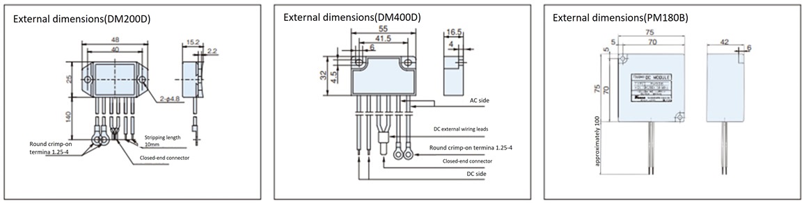
2. Rectifier (DC rectifier)
DC rectifier is built-in and already connected to the motor lead wires. If you wish to use DC external wiring circuit, please specify this when ordering, or connect according to this wiring diagram.
If you require a separate DC rectifier for use in a control panel, etc., please specify this when placing your order.
3. Brake section structure
*Manual release [Standard equipment: 0.1kW to 2.2kW]
- - Perform the release operation with no load applied to the output shaft.
- - Remove the fan cover and install the screws.
- After completing the work, be sure to remove the screws and attach the fan cover before starting operation.
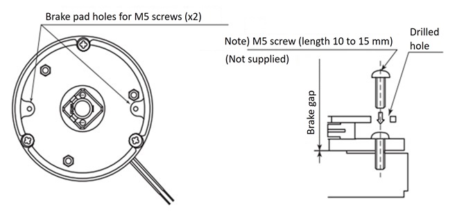
Note) 1.5kW and 2.2kW models use M6 screws.

