technical data Reducer Worm Reducer Motor Specifications
Wiring
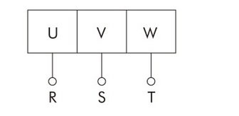
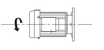
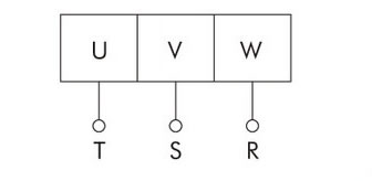
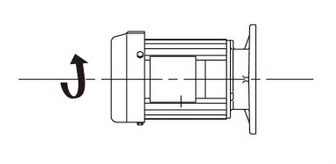
1. Rotation direction
| Motor Capacity | connection | Rotation direction | connection | Rotation direction |
|---|---|---|---|---|
| 0.1kW ~ 5.5kW |
 |
 |
 |
 |
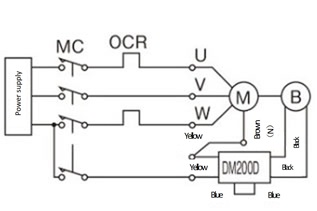
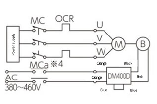
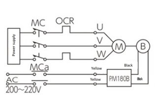
2. Brake motor wiring
- ・Standard products are shipped with AC internal wiring.
- ・Response times vary depending on the wiring, so refer to the diagram below and select the appropriate setting according to your application.
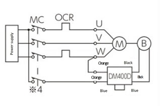
| Purpose | Three phase 200V | Three phase 400V | |||
|---|---|---|---|---|---|
| 0.1kW ~ 5.5kW | 0.1kW ~ 0.4kW | 0.75kW ~ 3.7kW | 5.5kW | ||
| AC internal wiring |
|
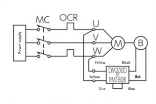
Only the 5.5kW model is PM180B. |
 |
 |
- |
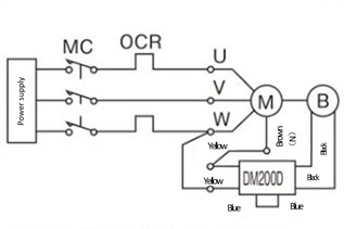
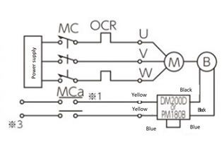
| AC external wiring |
|
Only the 5.5kW model is PM180B. |
 |
 |
- |
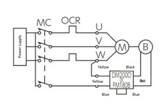
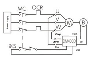
| AC external operation |
|
*3 The supply voltage for the brake marked with 3 is AC200V to AC254V for 0.1kW and 0.2kW. |
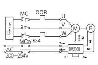
Note: Be sure to insulate the brown (N) wired with the closed-end connector from the terminal block. |
 |
 |
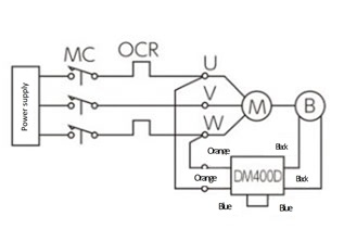
| DC external wiring |
|
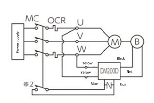
The PM180B cannot be switched to DC. |
 |
 |
- |
- M: Motor
- B: Brake
- MC: Magnetic contactor
- MCa: Auxiliary relay
- OCR: Overcurrent relay DM200D, PM180B, DM400D
- -N-: Protection element (varistor)
- Note 1) The brake voltage is DC 90V (when AC 200V is input to DM200D and PM180B).
- Note 2) When using DC external wiring, the brake power supply module may be damaged depending on the wiring length, wiring method, relay type, etc., so connect a varistor between the DC external wiring terminals. It is more effective to connect it close to the brake power supply module (to the blue lead wire). Specific varistor model numbers are listed below, but equivalent varistors can also be used. For the DM200D, select a varistor voltage of 470V. (The DM400D has a built-in varistor, so no external installation is required.)
Product name Manufacturer Model number When using the DM200D surge absorber Panasonic Corporation ERZV14D471 Ceramic varistor Nippon Chemi-Con Corporation TND14V-471KB00AAA0 - Note 3) Auxiliary relay (MCa) in *1 must have a contact capacity of AC200V7A or more (resistive load).
*2 If an MC auxiliary contact or Auxiliary relay is used, the contact capacity must be AC200V10A or more (resistive load). - Note 4) For Auxiliary relay (MCa) in *4, use one with a contact voltage of AC 400 to 440V and an inductive load of 1A or more.
- Note 5) For Auxiliary relay (MCa) of *5, use two or three units connected in series with a contact voltage of AC400 to 440V and an inductive load of 1A or more.

