technical data Reducer Small Gear Motor Motor Specifications
Wiring and rotation direction
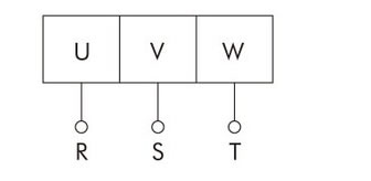
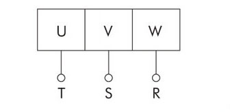
1. Wiring
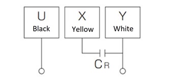
| With three-phase motor (40W to 5.5kW) | Single-phase motor (40W to 90W) | ||
|---|---|---|---|
 |
 |
 |
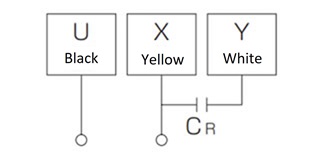 |
| A | B | A | B |
Note: The single-phase motor is a capacitor start type. A capacitor is included with the product, so please connect it before use.
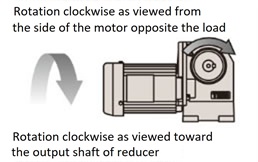
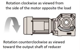
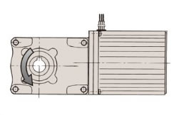
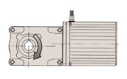
2.Rotation direction
The arrow in the diagram below indicates the direction of rotation as viewed from the output shaft in the case of connection A.
For connection B, rotate in the opposite direction to the arrow.
Gear Motor
| 2-stage reduction |
|---|
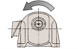 |
| 3-stage reduction |
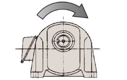 |
Hypoid Motor
| 2-stage/4-stage reduction |
|---|
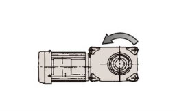 |
| 3-stage reduction |
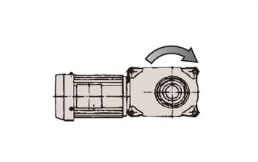 |
Croise Motor
| CSMA Series |
|---|
 |
| HCMA series |
 |
Hypoid Motor mini
| 2-stage reduction |
|---|
 |
| 3-stage reduction |
 |
Brake motor wiring
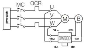
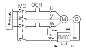
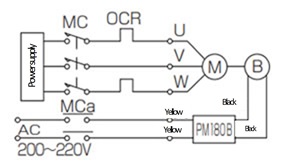
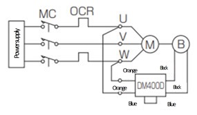
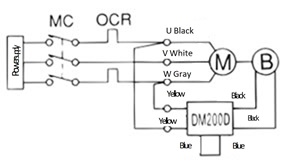
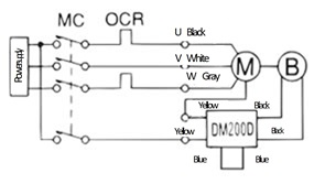
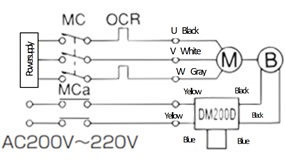
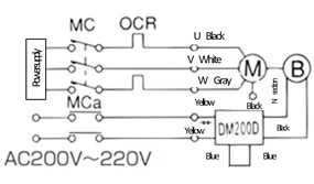
1. 200V class: 0.1kW to 5.5kW [Gear Motor, Hypoid Motor, Croise Motor]
- ・Standard products are shipped with AC internal wiring.
- ・Response times vary depending on the wiring, so refer to the diagram below and select the appropriate setting according to your application.
| Purpose | Gear Motor, Hypoid Motor, Croise Motor | |||
|---|---|---|---|---|
| Three phase 200V 0.1kW to 0.55kW |
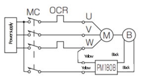
Three phase 200V 0.75kW to 3.7kW |
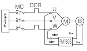
Three phase 200V 5.5kW |
||
| AC internal wiring |
|
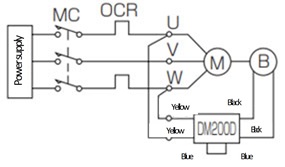 |
 |
 |
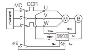
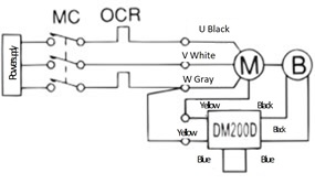
| AC external wiring |
|
 |
 |
 |
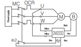
| AC external operation |
|
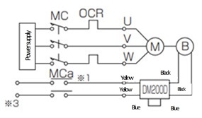
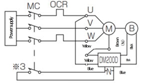
*3 The brake supply voltage is |
*3 The brake supply voltage is |
 |
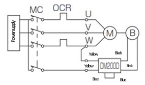
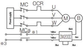
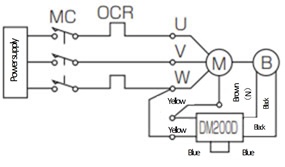
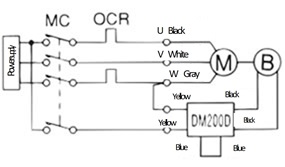
| DC external wiring |
|
 |
 |
- |
- M: Motor
- B: Brake
- MC: Magnetic contactor
- MCa: Auxiliary relay
- OCR: Overcurrent relay
- DM200D, PM180B: DC rectifier
- -N-: Protection element (varistor)
- Note 1) The brake voltage is DC 90V (when AC 200V is input to DM200D and PM180B).
- Note 2) When using DC external wiring, the brake power supply module may be damaged depending on the wiring length, wiring method, relay type, etc., so connect a varistor between DC external wiring terminals. It is more effective to connect it near the brake power supply module (to the blue lead wire). Specific varistor model numbers are listed below, but equivalent varistors can also be used. For the DM200D, select a varistor voltage of 470V.
Product name Manufacturer Model number When using the DM200D surge absorber Panasonic Corporation ERZV14D471 Ceramic varistor Nippon Chemi-Con Corporation TND14V-471KB00AAA0 - Note 3) Auxiliary relay (MCa) in *1 must have a contact capacity of AC200V7A or more (resistive load).
*2 If an MC auxiliary contact or Auxiliary relay is used, the contact capacity must be AC200V10A or more (resistive load).
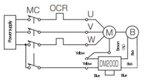
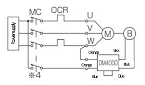
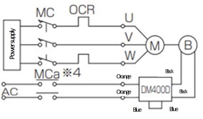
2. 400V class: 0.1kW to 5.5kW [Gear Motor, Hypoid Motor, Croise Motor]
- ・Standard products are shipped with AC internal wiring. (*Please consult us separately for 5.5kW.)
- ・Response times vary depending on the wiring, so refer to the diagram below and select the appropriate setting according to your application.
| Purpose | Gear Motor, Hypoid Motor, Croise Motor | |||
|---|---|---|---|---|
| Three phase 400V 0.1kW to 0.55kW |
Three phase 400V 0.75kW to 3.7kW |
Three phase 400V 5.5kW |
||
| AC internal wiring |
|
 |
 |
- |
| AC external wiring |
|
 |
 |
- |
| AC external operation |
|
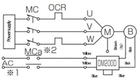
Note: Be sure to insulate the brown (N) wired with the closed-end connector from the terminal block. |
0.75kW and 3.7kW are AC380V to AC440V |
 |
| DC external wiring |
|
 |
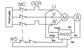 |
- |
- M: Motor
- B: Brake
- MC: Magnetic contactor
- MCa: Auxiliary relay
- OCR: Overcurrent relay
- DM200D, DM400D, PM180B: DC rectifier
- -N-: Protection element (varistor)
- Note 1) The brake voltage is DC 90V (when AC 200V is input to DM200D).
- Note 2) When using DC external wiring, the brake power supply module may be damaged depending on the wiring length, wiring method, relay type, etc., so connect a varistor between the DC external wiring terminals. It is more effective to connect it close to the brake power supply module (to the blue lead wire). Specific varistor model numbers are listed below, but equivalent varistors can also be used. For the DM200D, select a varistor voltage of 470V. (The DM400D has a built-in varistor, so no external installation is required.)
Product name Manufacturer Model number When using the DM200D surge absorber Panasonic Corporation ERZV14D471 Ceramic varistor Nippon Chemi-Con Corporation TND14V-471KB00AAA0 - Note 3) The 5.5kW DC rectifier PM180B is shipped as an accessory, so the customer must wire it themselves. The dimensional drawing is posted here.
- Note 4) Auxiliary relay (MCa) in *2 must have a contact capacity of AC200V7A or more (resistive load).
*3 If you use an MC auxiliary contact or Auxiliary relay, the contact capacity must be AC200V10A or more (resistive load).
*4 For Auxiliary relay (MCa), use one with a contact voltage of AC400 to 440V and an inductive load of 1A or more.
*5 Auxiliary relay (MCa) should be used by connecting two or three units in series with a contact voltage of AC400 to 440V and an inductive load of 1A or more.
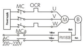
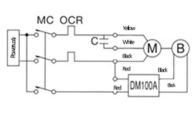
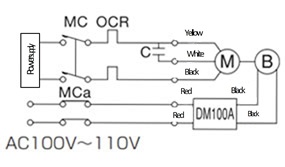
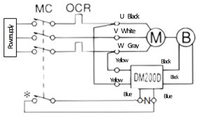
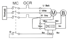
3. 40W, 60W, 90W [Hypoid Motor Mini Series]
- ・Standard products are shipped with AC internal wiring.
- ・Response times vary depending on the wiring, so refer to the diagram below and select the appropriate setting according to your application.
| Purpose | Three-phase motor standard voltage 200V class |
Three-phase motor voltage doubler 400V class |
Single-phase motor 100V |
|
|---|---|---|---|---|
| AC internal wiring |
|
 |
 |
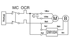 |
| AC external wiring |
|
 |
 |
 |
| AC external operation |
|
 |
Note: Be sure to cut off the N part connected with the closed end connector and insulate the N part. |
 |
| DC external wiring |
|
 |
 |
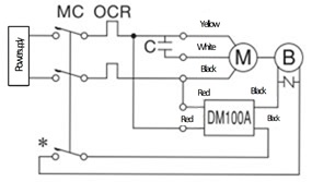 |
- M: Motor
- B: Brake
- MC: Magnetic contactor
- MCa: Auxiliary relay
- OCR: Overcurrent relay
- C: Capacitor (accessory)
- DM200D, DM100A: DC rectifier
- -N-: Protection element (varistor)
- Note 1) After wiring and before turning on the power, make sure that the yellow (or red) lead wire of DC rectifier is on the power supply side and the black is on the brake side.
- Note 2) DC rectifier has a built-in diode, so if it is shorted due to incorrect wiring, DC rectifier will be damaged.
- Note 3) Add protective elements to each contact as necessary.
- Note 4) When using an inverter, do not use it on a circuit other than that for AC external operation.
- Note 5) When using DC external wiring, the brake power supply module may be damaged depending on the wiring length, wiring method, relay type, etc., so connect a varistor between the DC external wiring terminals. It is more effective to connect it near the brake power supply module (to the blue lead wire). The specific varistor model numbers are as follows, but equivalent varistors can also be used. For the DM200D, select a varistor voltage of 470V.
Product name Manufacturer Model number For DM100A and DM200D surge absorber Panasonic Corporation ERZV14D471 Ceramic varistor Nippon Chemi-Con Corporation TND14V-471KB00AAA0 - Note 6) Capacitor for single-phase motor operation
40W: 15μF, 60W: 18μF, 90W: 27μF (all withstand voltage 220V). - Note 7) Please contact us for information on single-phase 200V.
*Heat generated by the motor
When a motor is running, all of its internal losses become heat, causing the motor to generate heat.
In particular, single-phase capacitor-run motors generate a lot of heat when the load factor is low, and depending on the conditions, the motor casing may exceed 90°C during operation, but this is not abnormal.
Please be careful as touching the motor carelessly or placing flammable materials nearby may result in an unexpected accident.

