technical data Top chain handling
Top chain Handling
3-1. Disassembling and reconnecting the chain
Note)
- 1. Please refer to Disassembly and Connection of Plastic modular chain.
- 2. Please use the disassembly and connection tools for the TTP, TT, TPS-KV, TPU-KV, TRU, TTKU, and TS types.
3-1-1. D-pin type joint pin (excluding TPUN555 type)
The chain can be disassembled from any point, and the pins can be inserted and removed from either the left or right side.
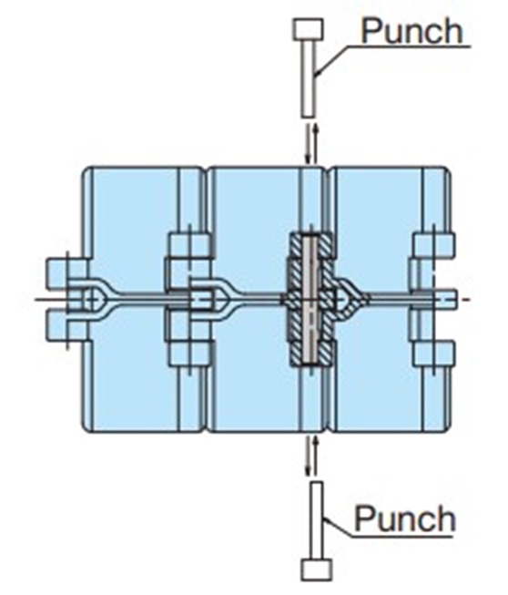
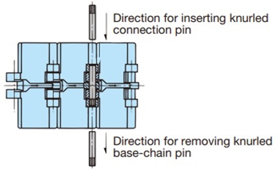
3-1-2. The joint pin is a knurled pin type
When disassembling, use a punch on the end without knurling to remove the part. When reconnecting, use a punch on the end with knurling to reconnect the part.
(Only for TTPDH and TTPDH-LBP models, the knurled side will remain in the same direction even when reconnected.)
3-1-3. TTUPM838H type
The joint pin is a D-pin type, so it can be inserted and removed from either the left or right side. Please use a punch with an outer diameter of Φ6 to 7.5.
Be careful not to insert too much or too little.
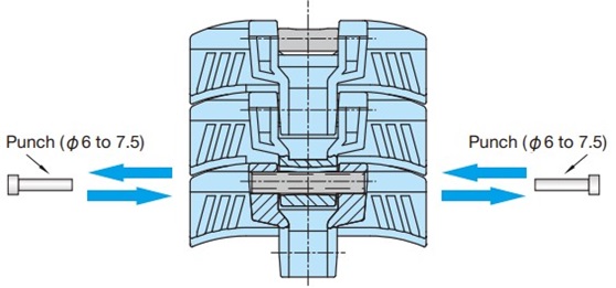
Using a punch with an outer diameter of Φ6 or less or Φ7.5 or more will damage the chain and pin.
3-1-4. TN/TNU/TRU/TP-PT/TP-PTS/TP-1873T
The pin at the joint and one side of the outer plate fit loosely together.
When disassembling at a location other than the joint, use a tool such as a chain vise to remove the pair of pins in a parallel position.
Please note that links that have been disassembled other than at the joints cannot be reused.
3-1-5. TP-1843G type/TP-1873G type
One brown and one white top plate for the joints are included. The white top plate can be used to distinguish the joints.
The pin at the joint and one side of the outer plate fit loosely together.
When disassembling at a location other than the joint, use a tool such as a chain vise to remove the pair of pins in a parallel position.
Please note that links that have been disassembled other than at the joints cannot be reused.
3-1-6. ST/RT type
All pins and plates are loose-fitting and can be disassembled from any point on the chain. Pins can also be inserted and removed from either the left or right side.
3-1-7. TO/TU type
Remove the pin from the other side of the top plate.
3-1-8. TS type
The chain can be disassembled from any part by removing the pin from the cotter pin side.
3-1-9. TTKU type
The pin at the joint and one side of the outer plate fit loosely together.
If disassembling at a location other than the joint, the pins are fastened in place, so use a grinder to grind off the ends of the pins and remove the pair of pins parallel to each other.
Please note that links that have been disassembled other than at the joints cannot be reused.
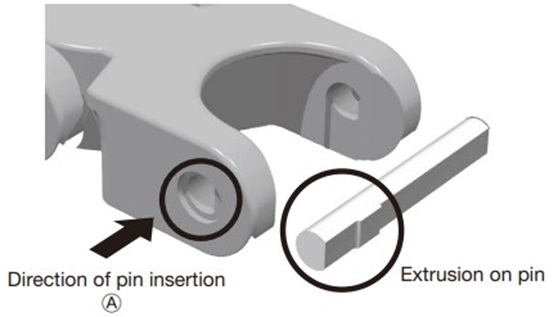
3-1-10. TPUN555 type
The pin can only be inserted in one direction. Use a punch to press against the pin end face on the opposite side to the insertion direction and remove it.
3-1-11. Plastic Crescent Chain
1. Remove the snap pin from the connecting pin and remove the offset link.
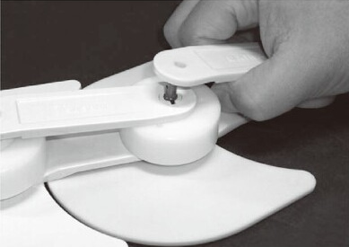
2. Rotate the offset link 90 degrees.

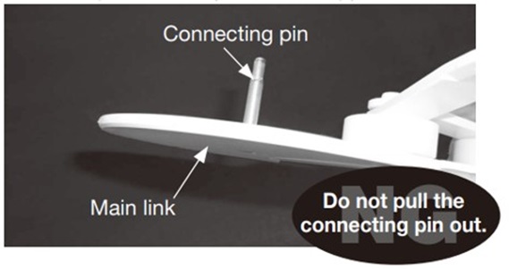
3. Remove the connecting pin along with the main link from the previous link.
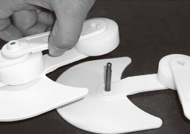
Note: When disassembling, do not remove the coupling pin from the main link.
3-2. Precautions for use of plastic pin type and disassembly/connection
| Eligible products | TTP-P type, TTPH-P type, TPS-P type, TPH-P type, TPM-P-SN type, TTUP-P type, TTUPM-P type, TTUPM-PC type, TPU-P type, TTUPM838H type, TPUSR-P type, TP-UB36P type, RSP40P type, RSP60P type, RSP60P-CU type |
|---|
- 1. Perform a slow start and slow stop.
- 2. Do not apply initial tension to the chain.
- 3. When cut and connect chains, engineering plastic pins are used. If a pin that has already been removed is reused, the fitting force will decrease, which may cause the pin to come out.
Be sure to follow the instructions below when cut and connect the chain. - 4. Plastic modular chain are listed in the selection section.
- 5. Chains with engineering plastic pins should not be used in wet conditions at temperatures exceeding 60°C.
Connecting D-pin
- 1) When connecting, please use the dedicated D-pins provided (main body pin: white, joint pin: orange).
- 2) The coupling pin is orange to distinguish it from the main body D pin (white).
- 3) One D-pin joint is included with each chain.
Cutting and joining instructions
(1) During disassembly
- 1) Place a punch with an outer diameter slightly smaller than the pin hole in the link on the end face of the D-pin and lightly hit it with a hammer to remove the pin. You can remove it from either the left or right direction.
- 2) Do not reuse D-pins once they have been removed.
(2) When connected
- 1) Please use the dedicated D-pin joint (orange).
- 2) Place a punch on the end of the D-pin and lightly hit it with a hammer to insert the D-pin into the pin hole in the link.
Insertion is possible from either the left or right side. Do not cut or join at the point where the joint pin (orange) is already inserted. - 3) Check that the connected D-pins are inserted evenly from the hinge end face on both sides.
- 4) Check that the connected chains bend smoothly.

