technical data Top chain Selection
If you would like to see the selection procedures and important points, please proceed below.
If you would like to narrow down or tentatively select a product series,
Please click here.
If your usage conditions have been decided and you would like a detailed selection,
Please click here.
Plastic modular chain (wide) selection procedure
Please follow the steps below to select Plastic modular chain (wide) and wearstrip that are best suited to your transport conditions.
(Click on each item to scroll to the main text.)
- 1. Check the transport conditions
- 2. Chain specification selection
- 3.Selection of wearstrip material
- 4. Determination of coefficients
- 5. Calculating the tension acting on the chain
- 6. Determine chain type and width
Note)
- 1. If you are selecting the BTM8H, WT2515F-W, WT3109-W, BTH16, or low-temperature (LTW) specifications, please fill out the inquiry sheet and contact us.
- 2. If you are selecting the WT2250VG or WT2250 flight type, please contact us.
Step 1. Check the transport conditions
Check the transport conditions.
Transportation condition confirmation items
| 1.Transported items | (1)Material |
|---|---|
| (2) Mass per piece (g/piece) | |
| (3) Shape | |
| (4) Dimensions (length x width x height) (diameter Φ x height) mm | |
| (5) Conveying direction | |
| 2.Transportation route | (1) straight running and curved transport |
| (2) Conveyor length m | |
| (3) Conveyor width mm | |
| (4) Transport layout | |
| (5) Space m | |
| 3.Transportation conditions | (1) Transport volume BPM/pieces |
| (2) Transfer interval mm | |
| (3) Conveyor speed m/min | |
| (4) Lubrication | |
| (5) Whether or not there is stock of transported goods (whether or not there is accumulation, and the percentage) (if yes, the length of accumulation: m) | |
| 4.Usage conditions | (1) Temperature ℃ |
| (2) Corrosive conditions such as chemicals, water, and humidity (see Corrosion resistance to various liquids) (if applicable, name of liquid) | |
| (3) Presence of glass fragments, paint chips, metal powder, sand, or other abrasive materials | |
| (4) Whether or not ultraviolet light is irradiated |
2-(3) Transport layout and other notes
Step 2. Select the chain specifications
Please select the chain specifications based on the environment and application.
Note)
- 1. Please refer to each product page for chain pitch, compatible chain specifications, and operating temperature ranges for each chain type.
- 2. For corrosion resistance, please refer to corrosion resistance against various liquids.
Step 3. Select wearstrip material
Select the appropriate wearstrip material from the chain specifications.
Table 1. Selection table for wearstrip materials
| Chain | wearstrip material | Lubrication | |||
|---|---|---|---|---|---|
| None | Yes | ||||
| abrasive inclusions | |||||
| None | Yes | None | Yes | ||
| Plastic modular chain (wide) ・For straight running ・For curved transport |
Stainless | B | D | A | A |
| steel | A | C | B | B | |
| Plastic rail (P-Rail) | D | × | A | × | |
| PLF rail | B | × | A | × | |
| M rail SJ-CNO |
A | × | × | × | |
Note)
- 1. "A": Highly recommended, "B": Recommended, "C": Recommended among acceptable, "D": Acceptable, "×": Inappropriate.
- 2. For heat-resistant/high-speed (KV) specifications, use stainless steel or steel wearstrip at normal temperatures, and stainless steel wearstrip at high temperatures.
- 3. Recommended metal wearstrip = cold rolled material.
- 4. Steel rails are shown for oil lubrication.
Plastic rail materials, exterior colors, and features
| Material and exterior color | Features | |
|---|---|---|
| Plastic rail (P rail) |
Ultra-high molecular weight polyethylene (Appearance color: white or green) |
・The most common rail ・Machined or extruded products ・Plastic Top chain are recommended for use in wet conditions. - It has low water absorption and is also highly resistant to chemicals and impacts. |
| PLF rail | Low Friction / Wear resistant Ultra-high molecular weight polyethylene (Exterior color: white) |
・Rails with lower friction and more wear resistance than P rails ・Machined or extruded products |
| M rail SJ-CNO |
Special Polyamide (M rail: exterior color: blue) (SJ-CNO: Appearance color: Purple) |
・Rails for dry conditions - Wear-resistant rails ・Machined products |
Note: Operating temperature range
Plastic rail (P-rail), PLF rail: -20℃ to 60℃
M Rail SJ-CNO: -20℃ to 80℃
Step 4. Determine the coefficients
The coefficients in Table 2 are based on our own experimental data.
Differences may occur depending on the conditions of use, the atmosphere in which it is used, the shape and material (specifications) of the transported items, and how dirty the chain is.
Use each coefficient in the tension calculation in step 5.
Table 2. Dynamic friction coefficients (μ1, μ2) between Plastic modular chain and mating materials
| Counterpart | Lubrication conditions | Top plate specifications | |||||||||||
|---|---|---|---|---|---|---|---|---|---|---|---|---|---|
| Closed type, open type | Net Type | DIA | DIY | ||||||||||
| Normal note) 5 | LFB, NLF, MWS, CB, WR, HG |
ALF | KV150 | KV250 | HTW | MF | LFB, MWS |
ALF | |||||
| wearstrip Material (μ1) |
Plastic rail (P rail) M rail |
Dry/Water | 0.25 | 0.20 | 0.15 | - | - | 0.30 | 0.27 | 0.20 | 0.15 | 0.30 | 0.25 |
| Soapy water and oil | 0.15 | 0.13 | 0.11 | - | - | 0.20 | - | 0.13 | 0.11 | - | 0.12 | ||
| SJ-CNO | Dry/Water | 0.20 | 0.15 | 0.13 | - | - | - | - | 0.15 | 0.13 | 0.30 | 0.20 | |
| Soapy water and oil | 0.12 | 0.12 | 0.11 | - | - | - | - | 0.12 | 0.11 | - | 0.12 | ||
| PLF rail | Dry/Water | 0.18 | 0.14 | 0.12 | - | - | - | - | 0.14 | 0.12 | - | - | |
| soapy water | 0.12 | 0.12 | 0.11 | - | - | - | - | 0.12 | 0.11 | - | - | ||
| steel· stainless |
Dry/Water | 0.25 | 0.20 | 0.14 | 0.25 | 0.35 | 0.32 | 0.27 | 0.20 | 0.14 | 0.30 | 0.25 | |
| Soapy water and oil | 0.15 | 0.15 | 0.11 | - | - | 0.20 | - | 0.15 | 0.11 | - | 0.12 | ||
| Transported goods Material (μ2) |
Metal cans | Dry/Water | 0.25 | 0.20 | 0.14 | 0.23 | 0.35 | 0.35 | 0.28 | 0.13 | 0.10 | 0.30 | 0.25 |
| Soapy water and oil | 0.14 | 0.13 | 0.11 | - | - | 0.20 | - | 0.12 | 0.10 | - | 0.12 | ||
| glass bottle | Dry/Water | 0.22 | 0.14 | 0.10 | 0.18 | 0.35 | 0.22 | 0.25 | 0.11 | 0.10 | 0.25 | 0.22 | |
| Soapy water and oil | 0.14 | 0.14 | 0.10 | - | - | 0.10 | - | 0.11 | 0.10 | - | 0.12 | ||
| plastic containers | Dry/Water | 0.25 | 0.17 | 0.13 | 0.20 | - | 0.30 | 0.28 | 0.11 | 0.10 | 0.30 | 0.25 | |
| Soapy water and oil | 0.15 | 0.13 | 0.11 | - | - | 0.20 | - | 0.11 | 0.10 | - | 0.15 | ||
| Paper pack | Dry/Water | 0.31 | 0.29 | 0.22 | 0.35 | - | 0.35 | 0.38 | 0.20 | 0.15 | 0.38 | 0.30 | |
| Soapy water and oil | 0.20 | 0.21 | 0.12 | - | - | - | - | 0.19 | 0.11 | - | 0.20 | ||
Note)
- 1. This is the coefficient of dynamic friction at room temperature (below 50°C). At high temperatures (above 50°C), a coefficient of dynamic friction of 0.35 should be applied.
- 2. The dynamic friction coefficient data in the table above is based on in-house testing. The friction coefficient value may vary slightly depending on factors such as chain contamination and the shape of the bottom surface of the conveyed object.
In particular, the friction coefficient value for paper cartons and paper cans varies greatly depending on the bottom shape, paper material, etc., so we recommend measuring the friction coefficient for each transported item. - 3. M-rail and SJ-CNO are wearstrip designed exclusively for dry conditions.
- 4. In the case of water lubrication, depending on the type of transported object, the values may be greater than those in Table 2, causing adhesion.
- 5. Applicable: Standard Series, chemical resistant (Y) specifications, conductive (E) specifications, acid resistant (AR) specifications, ultraviolet resistant (UVR) specifications.
Table 3. Angle coefficient (αL) and length coefficient (αS) when using wearstrip
| Top Plate Material | Lubrication condition | Side bending angle | ||||||||
|---|---|---|---|---|---|---|---|---|---|---|
| 30° | 45° | 60° | 90° | 120° | 150° | 180° | ||||
| Angle coefficient (αL) | Polyacetal | B | No lubrication/water lubrication | 1.15 | 1.22 | 1.30 | 1.50 | 1.70 | 1.90 | 2.20 |
| Soapy water lubrication | 1.10 | 1.13 | 1.15 | 1.25 | 1.35 | 1.50 | 1.60 | |||
| LFG | No lubrication/water lubrication | 1.10 | 1.17 | 1.25 | 1.35 | 1.50 | 1.70 | 1.85 | ||
| Soapy water lubrication | 1.10 | 1.11 | 1.15 | 1.25 | 1.35 | 1.50 | 1.60 | |||
| HTW | No lubrication/water lubrication | 1.20 | 1.27 | 1.45 | 1.75 | 2.10 | 2.50 | 3.00 | ||
| Soapy water lubrication | 1.10 | 1.17 | 1.25 | 1.35 | 1.50 | 1.70 | 1.85 | |||
| Length factor (αS) | 0.5 | 0.8 | 1.0 | 1.6 | 2.1 | 2.6 | 3.1 | |||
Note: For flight-type inclined transport, apply the above coefficient according to the angle of inclination.
Step 5. Calculate the tension acting on the chain
Calculate the tension and required power acting on a general conveyor chain using the formula below.
Note) Please refer to the tension calculation examples for special conveyors (pasteurizers, warmers, coolers), nose bar conveyors (follower side, front side, both ends), forward/reverse bottom drive, and inclined conveyance.
Note: SI units and gravity units
The formula is written in both SI units and gravity units.
When calculating tension F in gravitational units, weight in gravitational units (kgf) is the same value as mass in SI units (kg).
Explanation of symbols
- F = tension acting on the chain kN{kgf}
- m1 = Approximate chain mass (kg/m)
"Calculation method for approximate chain mass"
Calculate the approximate mass of the chain per 1m length.
If the chain width you are considering using is A mm
m1 = Approximate chain mass (catalog value (kg/m 2)) x A/1000
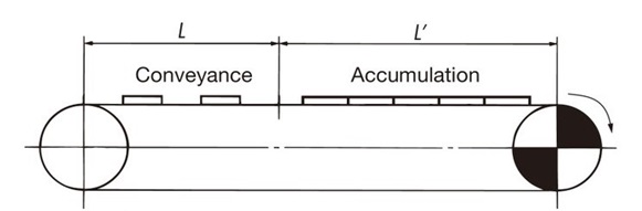
- S1 = length of conveying section (m)
- m2 = mass of material conveyed through the conveying section (kg/m)
- S2 = Length of accumulator (m)
- m3 = Accumulator conveyed mass (kg / m)
- μ1 = Coefficient of kinetic friction between the chain and wearstrip (see Table 2)
- μ2 = Dynamic friction coefficient between the chain and the conveyed object in the accumulation section (see Table 2)
- P = required power (kW)
- V = Chain speed (m/min)
- ηNote) = Mechanical transmission efficiency of the drive unit
SI units (kN)
Tension acting on the chain...(1)
F = 9.80665 × 10⁻³ { (2.1m1 + m2) S1・μ1 + (2.1m1 + m3) S2・μ1 + m3・S2・μ2 }
Required power
P = F ・ V 60 ηNote)
Gravity unit (kgf)
Tension acting on the chain...(1)
F = (2.1m1 + m2) S1・μ1 + (2.1m1 + m3) S2・μ1 + m3・S2・μ2
Required power
P = F ・ V 6120 ηNote)
Note)
- 1. Check the transmission mechanical efficiency of the drive unit used.
- 2. When selecting Plastic modular chain (mold-to-width), follow the Top chain selection procedure.
Calculation for curved transport (one curved section)
Basically, it is the same as for straight running. The tension acting on the corners is corrected by the angle coefficient.
A calculation example is shown for the transport route shown below.
For curved conveyance, in addition to the tension F acting on the chain, the tension Fα acting on the chain at the curved section must be calculated.
It is recommended to use lubrication when conveying on curves where the chain slides against wearstrip.
Particularly when the side bending angle exceeds 90°, the chain or wearstrip may wear unevenly in a relatively short period of time, which may cause the chain to lift up.
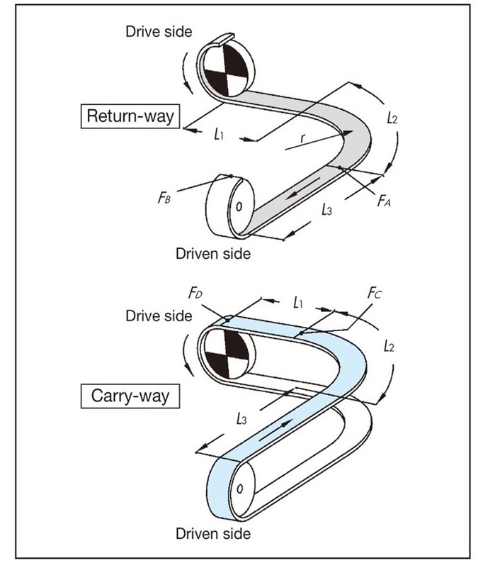
F = 9.80665 × 10⁻³ ・FD (kN) ... (1)
return-way tension
[A section tension: FA]
FA = m1(L1 + L2) μ1・αL 90°
L2 = r × αS 90°
[B part tension: FB]
FB = 1.1 ×(FA + m1・L3・μ1)
Transport side tension
[C part tension: FC]
FC ={FB + (m1 + m2) (L2 + L3) μ1 + m3 (L2 + L3) μ2}・αL 90°
L2 = r × αS 90°
[Tension acting on the chain at the curve: Fα]
Fα = Fc × 2
The chain can be used as long as Fα is equal to or less than Maximum allowable load in the curved section of the chain. Calculate Maximum allowable load in the curved section by taking into account the conveyor speed and ambient temperature when using the chain, referring to the curved conveyor chain Allowable load graph. Please refer to each product page for the chain Allowable load graph.
[D part tension: FD]
FD = FC + {(m1 + m2) L1・μ1 + m3・L1・μ2}
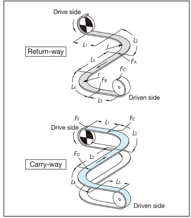
Calculation of curved conveyance (two curved sections)
When sliding wearstrip or other device on a curved section, limit the number of 90-degree curves to two, as this may cause chain pulsation.
If you want to install more curves, consider splitting the conveyor.
For curved conveyance, in addition to the tension F acting on the chain, the tension Fα acting on the chain at the curved section must be calculated.
F = 9.80665 × 10⁻³ ・FF (kN) ... (1)
return-way tension
[A section tension: FA]
FA = m1(L1 + L2) μ1・αL 90°
L2 = r × αS 90°
[B part tension: FB]
FB = {FA + m1(L3 + L4) μ1} αL 90°
L4 = r × αS 90°
[C part tension: FC]
FC = 1.1 × (FB + m1・L5・μ1)
Transport side tension
[D part tension: FD]
FD = {FC + (m1 + m2) (L4 + L5) μ1 + m3(L4 + L5) μ2}・αL 90°
L4 = r × αS 90°
[Tension at E section: FE]
FE = {FD + (m1 + m2) (L2 + L3) μ1 + m3(L2 + L3) μ2}・αL 90°
L2 = r × αS 90°
[Tension acting on the chain at the curve: Fα]
Fα = FE × 2
The chain can be used as long as Fα is equal to or less than Maximum allowable load in the curved section of the chain. Calculate Maximum allowable load in the curved section by taking into account the conveyor speed and ambient temperature when using the chain, referring to the curved conveyor chain Allowable load graph. Please refer to each product page for the chain Allowable load graph.
[F part tension: FF]
FF = FE + {(m1 + m2) L1・μ1 + m3・L1・μ2}
Calculation of inclined conveyance (incline only)
Note: SI units and gravity units
The formula is written in both SI units and gravity units.
When calculating tension F in gravitational units, weight in gravitational units (kgf) is the same value as mass in SI units (kg).
Explanation of symbols
- F = tension acting on the chain kN{kgf}
- m1 = Approximate chain mass (kg/m)
"Calculation method for approximate chain mass"
Calculate the approximate mass of the chain per 1m length.
If the chain width you are considering using is A mm
m1 = Approximate chain mass (catalog value (kg/m 2)) x A/1000
- m2 = mass of material conveyed through the conveying section (kg/m)
- μ1 = Coefficient of kinetic friction between the chain and wearstrip (see Table 2)
- αL = angle coefficient of the curve between horizontal and inclined (see Table 3)
- αS = length factor (see Table 3)
- θ = tilt angle (degrees)
- r = radius of the curve between the horizontal and the inclined section (m)
- P = required power (kW)
- V = Chain speed (m/min)
- ηNote) = Mechanical transmission efficiency of the drive unit
Note: Please check the drive unit used to determine transmission mechanical efficiency.
Table 4. Guide to inclined conveying angles
| Chain Material | No lubrication (dry) | Soapy water lubrication | oil lubrication |
|---|---|---|---|
| Steel | 10 degrees | - | 6 degrees |
| Standard Series (polyacetal) | 5 degrees | 3 degrees | - |
| Rubber type | 20 degrees | - | - |
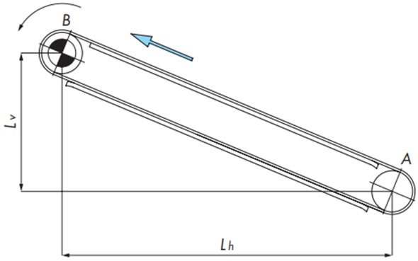
F = 9.80665 × 10⁻³ ・FB (kN) ... (1)
return-way tension
[A section tension: FA]
FA = 1.1m1 (Lh・μ1 - Lv)
If FA < 0, then FA = 0
Transport side tension
[B part tension: FB]
FB = FA + {(m1 + m2) (Lh・μ1 + Lv)}
Chain tension
F = FB
Step 6. Determine chain type and width
- The tension F (kN) acting on the chain calculated using formula (1) is converted into the tension F' (kN/m) acting per meter of chain width.
F' = 1000 F Chain width (mm) ...... (2)
- Select a type and width of Plastic modular chain that has Maximum allowable load greater than the applied tension F' per meter of chain width calculated using formula (2).
Note)
- 1. Under wet conditions, the maximum operating temperature is 60°C. (Maximum 105°C for high-temperature (HTW) specifications only. Maximum 250°C for heat-resistant, high-speed (KV250) specifications only. Cannot be used with heat-resistant, high-speed (KV150) specifications.)
- 2. Calculate Maximum allowable load by taking into account the conveyor speed and ambient temperature while referring to Allowable load graph. Please refer to each product page for Allowable load graph.
- 3. If Maximum allowable load is insufficient, a larger chain can be selected. Also, the conveyor's operating environment should be taken into consideration when determining the chain type.

