technical data Selecting Small size conveyor chain
If you would like to see the selection procedures and important points, please proceed below.
If you would like to narrow down or tentatively select a product series,
Please click here.
If your usage conditions have been decided and you would like a detailed selection,
Please click here.
Free flow chain selection
Step 1. Check the transport conditions
- (1) Type, mass, dimensions, and quantity of transported items (including pallets)
- (2) Conveyor speed
- (3) Conveyor length (length of accumulation section and conveying section)
- (4) Atmosphere
Step 2. Select the chain type
The specifications of the chain body and rollers are determined based on the operating conditions and environment.
Step 3. Tentatively decide on the chain type
Perform a preliminary check of the chain tension.
- SI units: F = 9.80665 × WT × f × Kv/1000
- Gravity unit: F = WT × f × Kv
Note: This catalog lists both SI units and gravity units.
When calculating maximum tension F in gravitational units, weight (kgf) is the same as mass (kg).
- F: Maximum tension acting on the chain kN {kgf}
- W T: Total mass of transported items excluding chain kg
- f: Friction coefficient f2 (Table 8) + f3 (Table 9)
- Kv: Velocity coefficient (Table 13)
When two chains are used in parallel, the tension acting on the chains will not be uniform.
Taking into account the imbalance in applied tension, provisionally determine a chain type and size with Maximum allowable load (Tables 14 and 15) of F x 0.6 or more.
Maximum allowable load for Small size conveyor chain (excluding stainless steel and engineering plastic chains) is set at the fatigue limit.
If the load is below this value, Small size conveyor chain will not break even if repeated loads are applied.
*Stainless steel and engineering plastic Maximum allowable load is determined based on the surface pressure between the pin and bushing, taking into account wear performance.
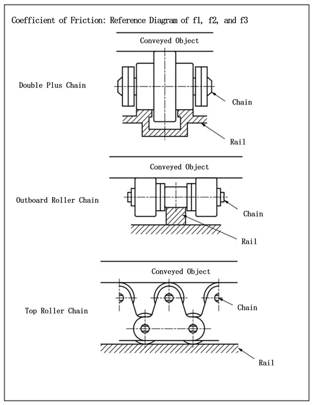
Table 7 f 1: Coefficient of friction between chain and rail during transport
| Chain Type | Chain body rollers | Lubrication (none) | Lubrication (with) | |
|---|---|---|---|---|
| Double Plus Free Flow Chains | Plastic Roller | A・B・C・D UA・UB |
0.08 | - |
| Steel roller | - | 0.05 | ||
| Center Roller Chain | Steel roller | - | 0.08 | |
| With outboard roller and With top roller chain |
Steel roller |
S Roller | (0.21) | 0.14 |
| R Roller | (0.12) | 0.08 | ||
| Plastic Roller | S Roller | - | - | |
| R Roller | 0.08 | - | ||
| Poly-steel chain | - | 0.25 | - | |
The values in parentheses are for reference only.
Table 8 f2: Friction coefficient between chain and conveyed object during accumulation
| Chain Type | Conveyor roller | Lubrication (none) | Lubrication (with) |
|---|---|---|---|
| Double Plus Free Flow Chains | A・C・UA | 0.10 | - |
| B・D・UB | 0.15 | - | |
| Steel roller | - | 0.10 | |
| Center Roller Chain | Steel roller | - | 0.06 |
| With outboard roller chain |
Plastic outboard roller | 0.06 | - |
| outboard roller with plastic brake | 0.20※ | - | |
| Steel outboard roller | (0.09) | 0.06 | |
| With top roller chain |
Plastic top Roller | 0.06 | - |
| Steel Top Roller | (0.09) | 0.06 |
The values in parentheses are for reference only.
Note) This indicates the friction coefficient per plastic brake outboard roller. If the brake outboard roller account for approximately 1/3 of the total number of outboard roller the friction coefficient will be 0.1.
(For RF Double pitch see here, and for RS type, see here for outboard roller mounting positions.)
Table 9 f3: Friction coefficient between chain and rail during accumulation
| Chain Type | Chain body rollers | Lubrication (none) | Lubrication (with) | |
|---|---|---|---|---|
| Double Plus Free Flow Chains | A・C・UA | 0.20 | - | |
| B・D・UB | 0.25 | - | ||
| Steel roller | - | 0.10 | ||
| Center Roller Chain | Steel roller | - | 0.10 | |
| With outboard roller and With top roller chain |
Steel roller |
S Roller | (0.21) | 0.14 |
| R Roller | (0.12) | 0.08 | ||
| Plastic Roller | S Roller | - | - | |
| R Roller | 0.08 | - | ||
| Poly-steel chain | - | 0.25 | - | |
The values in parentheses are for reference only.
Step 4. Check the allowable load of the roller
This is a guideline value that does not cause roller rotation problems, assuming use in a lubricated state.
The load acting on the rollers should be below the values below. The values for steel rollers are in a lubricated state.
1. Double Plus Free Flow Chains and center roller chains
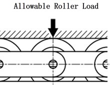
・For RF2030 to RF2080
Indicates the allowable transport load per two chains (allowable load per 1m of pallet length).
Table 10 Allowable roller load
| Size | Chain body rollers | frame | ||
|---|---|---|---|---|
| Aluminum frame | With steel rails Aluminum frame |
|||
| RF2030 | Plastic Roller | A・B・C・D | 0.39 {40} | 0.78 {80} |
| UA・UB | 0.20 {20} | 0.20 {20} | ||
| Steel roller | - | 1.57 {160} | ||
| RF2040 | Plastic Roller | 0.59 {60} | 1.18 {120} | |
| Steel roller | - | 2.35 {240} | ||
| RF2050 | Plastic Roller | 0.78 {80} | 1.57 {160} | |
| Steel roller | - | 3.14 {320} | ||
| RF2060 | Plastic Roller | 0.98 {100} | 1.96 {200} | |
| Steel roller | - | 3.92 {400} | ||
| RF2080 | Plastic Roller | - | 2.94 {300} | |
| Steel roller | - | 5.88 {600} | ||
2. Chains with outboard roller and top rollers
Please check the allowable load on both outboard roller, top rollers and the rollers on the chain body.
1) Roller allowable load
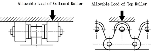
Table 11 Allowable roller load
| Size | outboard roller and single strand top roller |
Double-row top roller | ||
|---|---|---|---|---|
| Plastic Roller | Steel roller | Stainless steel roller | Steel roller | |
| RF2040・RS40 | 0.05 {5} | 0.15 {15} | 0.05 {5} | 0.29 {30} |
| RF2050・RS50 | 0.07 {7} | 0.20 {20} | 0.06 {6} | 0.39 {40} |
| RF2060・RS60 | 0.10 {10} | 0.29 {30} | 0.09 {9} | 0.59 {60} |
| RF2080・RS80 | 0.18 {18} | 0.54 {55} | 0.15 {15} | 1.08 {110} |
| RF2100・RS100 | 0.29 {30} | 0.78 {80} | 0.25 {25} | 1.57 {160} |
Note) The allowable roller load of lambda rollers is the same as that of steel rollers.
2) Allowable load on the rollers of the chain body
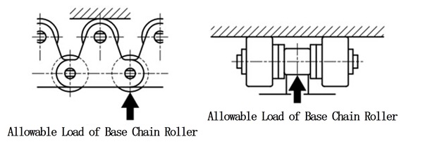
Table 12 Allowable load on rollers of chain body
| Size | Steel roller | Plastic Roller | Poly-steel chain | Stainless steel roller | ||
|---|---|---|---|---|---|---|
| R Roller | S Roller | R Roller | R Roller | S Roller | ||
| RF2040・RS40 | 0.64 {65} | 0.15 {15} | 0.20 {20} | 0.02 {2} | 0.20 {20} | 0.05 {5} |
| RF2050・RS50 | 0.98 {100} | 0.20 {20} | 0.29 {30} | 0.04 {4} | 0.29 {30} | 0.06 {6} |
| RF2060・RS60 | 1.57 {160} | 0.29 {30} | 0.49 {50} | 0.06 {6} | 0.49 {50} | 0.09 {9} |
| RF2080・RS80 | 2.65 {270} | 0.54 {55} | 0.88 {90} | - | 0.78 {80} | 0.15 {15} |
| RF2100・RS100 | 3.92 {400} | 0.78 {80} | 1.27 {130} | - | 1.18 {120} | 0.25 {25} |
Note)
- 1. For Poly-steel chain, the allowable load is per plastic Inner link.
- 2. Lambda Chain are the same as steel rollers.
- 3. Guide channel material for the main steel R roller should be high tensile strength material of S45C or higher.
- 4. Plastic Roller include KV specifications.
Step 5. Calculate the tension (F) acting on the chain
SI units
F =
G
1000
× {(W1 + M) × L1 × f1 + W2 × L2 × f2
+ (W2 + M) × L2 × f3 + 1.1 × M × (L1 + L2) × f1}
kW = F・V 60 × 1 η
Gravity Units
F = (W1 + M) × L1 × f1 + W2 × L2 × f2 + (W2 + M) × L2 × f3
+ 1.1 × M × (L1 + L2) × f1
kW = F・V 6120 × 1 η
- F: Maximum tension acting on the chain: kN{kgf}
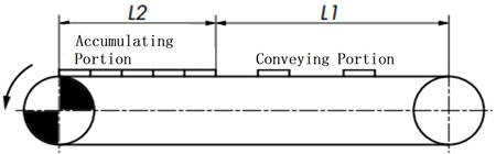
- L 1: Length of conveying section: m
- W 1: Amount of material conveyed in the conveying section: kg/m
- L2: Length of accumulation section: m
- W 2: Amount of material conveyed in the accumulator: kg/m
- f 1: Friction coefficient between the chain and rail in the conveying section
- f2: Friction coefficient between the chain and the conveyed object in the accumulation section
- f3: Friction coefficient between the chain and rail in the accumulation section
- M: Chain mass: kg/m
- kW: Required power: kW
- V: Chain speed: m/min
- η: Mechanical transmission efficiency of the drive unit
- G: Gravitational acceleration: 9.80665m/s 2
In the case of free flow conveyors, two chains are generally used in parallel, so the mass of the chain is the mass of two chains. Therefore, F is the maximum tension acting on the two chains.
However, taking into consideration the imbalance of the acting tension, 0.6F is assumed to act on each piece.
Step 6. Determine the chain size
Multiply the maximum tension (0.6F) acting on a single chain by the speed coefficient (Kv) from Table 13 to select a chain that satisfies the following formula.
0.6F × Kv ≦ Maximum allowable load
Maximum allowable load for Small size conveyor chain (excluding stainless steel and engineering plastic chains) is set at the fatigue limit.
If the load is below this value, Small size conveyor chain will not break even if repeated loads are applied.
*Stainless steel and engineering plastic Maximum allowable load is determined based on the surface pressure between the pin and bushing, taking into account wear performance.
Table 13 Speed coefficient (Kv)
| Chain speed m/min | Velocity Factor (Kv) |
|---|---|
| 15 or less | 1.0 |
| 15~30 | 1.2 |
| 30~50 | 1.4 |
| 50~70 | 1.6 |
| 70~90 | 2.2 |
| 90~110 | 2.8 |
| 110~120 | 3.2 |
Recommended speeds for the chains listed below are:
- Double Plus Free Flow Chains: 5 to 15 m/min or less
- Plastic R roller chain: 70m/min or less
- Poly-steel chain: 70m/min or less
Table 14 Maximum allowable load (1)
| Size & Roller Type | Chain body specifications | Roller type | |
|---|---|---|---|
| A・C・UA | B・D・UB | ||
| RF2030VRP | Standard Series | 0.55 {56} | 0.27 {28} |
| HCP specifications | |||
| Lambda Specification | |||
| SS Series | 0.27 {28} | ||
| RF2040VRP | Standard Series | 0.88 {90} | 0.44 {45} |
| HCP specifications | |||
| Lambda Specification | |||
| SS Series | 0.44 {45} | ||
| RF2050VRP | Standard Series | 1.37 {140} | 0.69 {70} |
| HCP specifications | |||
| Lambda Specification | |||
| SS Series | 0.69 {70} | ||
| RF2060VRP | Standard Series | 2.06 {210} | 1.03 {105} |
| HCP specifications | |||
| Lambda Specification | |||
| SS Series | 1.03 {105} | ||
| RF2080VRP | Standard Series | 5.30 {540} | 2.65 {270} |
| HCP specifications | |||
| Lambda Specification | |||
| SS Series | 2.65 {270} | ||
| Size & Roller Type | Chain body specifications | Roller type | |
|---|---|---|---|
| Steel specifications (Double Plus Free Flow Chains) |
Center Roller (constant velocity) |
||
| RF2030VR | Standard Series | 0.98 {100} | - |
| RF2040VR・CR | Standard Series | 1.57 {160} | 1.57 {160} |
| RF2050VR・CR | Standard Series | 2.45 {250} | 2.45 {250} |
| RF2060VR・CR | Standard Series | 3.73 {380} | 3.73 {380} |
| RF2080VR・CR | Standard Series | 5.30 {540} | 5.30 {540} |
Table 15 Maximum allowable load (2)
| Size | Chain Type | ||||||
|---|---|---|---|---|---|---|---|
| Chain with outboard roller | single strand top roller chain | ||||||
| Steel roller |
Plastic R Roller |
Poly-steel chain | Stainless steel roller |
Steel roller |
Plastic R Roller |
Stainless steel roller |
|
| RF2040・RS40 | 2.65 {270} | 0.44 {45} | 0.44 {45} | 0.69 {70} | 2.65 {270} | 0.44 {45} | 0.69 {70} |
| RF2050・RS50 | 4.31 {440} | 0.69 {70} | 0.69 {70} | 1.03 {105} | 4.31 {440} | 0.69 {70} | 1.03 {105} |
| RF2060・RS60 | 6.28 {640} | 1.03 {105} | 0.88 {90} | 1.57 {160} | 6.28 {640} | 1.03 {105} | 1.57 {160} |
| RF2080・RS80 | 10.7 {1090} | 1.77 {180} | - | 2.65 {270} | 10.7 {1090} | 1.77 {180} | 2.65 {270} |
| RF2100 | 17.1 {1740} | 2.55 {260} | - | 2.55 {260} | 17.1 {1740} | 2.55 {260} | 2.55 {260} |
| RS100 | 3.82 {390} | 3.82 {390} | |||||
Note)
- 1. Lambda specifications are the same as the steel rollers in the table above.
- 2. Maximum allowable load of a double-strand top roller chain is 1.7 times that of single strand top roller chain, except for the lambda chain, which is 1.4 times.

