technical data Selecting Small size conveyor chain
If you would like to see the selection procedures and important points, please proceed below.
If you would like to narrow down or tentatively select a product series,
Please click here.
If your usage conditions have been decided and you would like a detailed selection,
Please click here.
Small size conveyor chain Selection Procedure
The appropriate chain size and type are selected depending on the type and capacity of the conveyor. Various cases can be considered depending on the conditions of use of the conveyor, and it may not be possible to make a general decision, but generally the following procedure is followed.
1. Check the transport conditions
2. Tentative decision on chain type
3. Check the allowable load of the roller and attachment
4. Calculation of maximum tension acting on the chain
5. Determine chain size
6. Chain Selection Method for Intermittent Operation
Step 1. Check the transport conditions
- 1. Type of conveyor (slat conveyor, bucket conveyor, etc.)
- 2. Conveying direction (horizontal, inclined, vertical conveying)
- 3. Type, mass and dimensions of the transported item
- 4. Transport volume and transport interval
- 5. Conveyor speed
- 6. Conveyor length
- 7. Lubrication
- 8. Transport atmosphere (temperature, corrosion factors)
Step 2. Tentatively decide on the chain type
Determine the maximum static tension (F) acting on the chain.
SI units F(kN) = W × f 1 × K V × G 1000
Gravity unit F{kgf} = W × f 1 × K V
W = Total mass of items on the conveyor {weight} kg {kgf}
f 1 = friction coefficient (Table 3) K V = velocity coefficient (Table 4)
G = 9.80665m/s2
F (or F × 0.6 when the chains are parallel) or more Maximum allowable load had
The chain type and size will be tentatively determined.
Maximum allowable load for Small size conveyor chain (excluding stainless steel and engineering plastic chains) is set at the fatigue limit.
If the load is below this value, Small size conveyor chain will not break even if repeated loads are applied.
*Stainless steel and engineering plastic Maximum allowable load is determined based on the surface pressure between the pin and bushing, taking into account wear performance.
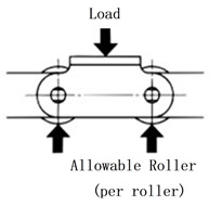
Step 3. Check the allowable load
The load acting on rollers or attachments in load-type conveyors should be less than the values in Tables 1 and 2.
Table 1 Allowable load of main roller
| Size | Double pitch RS type with attachment (Standard Series) Lambda/Long-life Lambda |
Stainless steel roller (SS, AS) |
Plastic Roller | Plastic Roller KV specifications |
Low noise Plastic Roller |
Poly-steel chain | |||
|---|---|---|---|---|---|---|---|---|---|
| R Roller | S Roller | R Roller | S Roller | R Roller | S Roller | R Roller | R Roller | ||
| RS25 | - | - | - | - | - | - | - | - | 0.005 {0.5} |
| RS35 | - | - | - | - | - | - | - | - | 0.015 {1.5} |
| RF2040・RS40 | 0.64 {65} | 0.15 {15} | 0.20 {20} | 0.05 {5} | 0.20 {20} | 0.02 {2} | 0.20 {20} | 0.14 {14} | 0.02 {2.0} |
| RF2050・RS50 | 0.98 {100} | 0.20 {20} | 0.29 {30} | 0.06 {6} | 0.29 {30} | 0.03 {3} | 0.29 {30} | 0.21 {21} | 0.04 {4.0} |
| RF2060・RS60 | 1.57 {160} | 0.29 {30} | 0.49 {50} | 0.09 {9} | 0.49 {50} | 0.05 {5} | 0.49 {50} | 0.34 {35} | 0.06 {6.0} |
| RF2080・RS80 | 2.65 {270} | 0.54 {55} | 0.78 {80} | 0.15 {15} | 0.88 {90} | 0.09 {9} | - | 0.62 {63} | - |
| RF2100・RS100 | 3.92 {400} | 0.78 {80} | 1.18 {120} | 0.25 {25} | 1.27 {130} | - | - | - | - |
| RF2120・RS120 | 5.88 {600} | 1.18 {120} | 1.77 {180} | 0.34 {35} | - | - | - | - | - |
| RS140 | - | 1.32 {135} | - | 0.39 {40} | - | - | - | - | - |
| RF2160・RS160 | 9.61 {980} | 1.91 {195} | 2.75 {280} | 0.54 {55} | - | - | - | - | - |
| With BS attachment | |
|---|---|
| Size | Standard Series |
| RF06B | 0.073 {7} |
| RS08B | 0.15 {15} |
| RS10B | 0.2 {20} |
| RS12B | 0.29 {30} |
| RS16B | 0.54 {55} |
| RS20B | 0.79 {81} |
| RS24B | 1.37 {140} |
Allowable load of main roller
Note)
- 1. Values are when lubricated. Double pitch and RS-type chains with attachments include environment-resistant chains (NP and NEP Series).
- 2. For Poly-steel chain, the allowable load per unit is when supported by the underside of Inner link.
- 3. For guide channel material of Standard Series R rollers, use a high tensile strength material of S45C or higher.
- 4. For information on Bearing Bush Chain and Bearing Cage Chain, please refer to Product Info page.
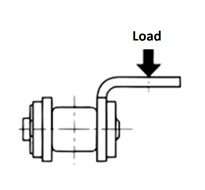
Table 2 Allowable load for attachment A
This is the vertical load that the A-type attachment can tolerate.
Depending on the shape and structure of the attachment you install, a twisting force may be generated on attachment A. Please contact us if this occurs.
| double pitch chain | RS type chain | ||||
|---|---|---|---|---|---|
| Size | Double pitch 1 | Stainless | Size | With attachmentNote 1 | Stainless |
| RF2040 | 0.262 {26.7} | 0.108 {11.0} | RS25 | 0.028 {2.9} | 0.012 {1.2} |
| RF2050 | 0.455 {46.4} | 0.189 {19.3} | RS35 | 0.094 {9.6} | 0.036 {3.7} |
| RF2060 | 1.06 {108} | 0.419 {42.7} | RS40 | 0.130 {13.3} | 0.054 {5.5} |
| RF2080 | 1.67 {170} | 0.646 {65.9} | RS50 | 0.243 {24.8} | 0.101 {10.3} |
| RF2100 | 2.51 {256} | 1.15 {117} | RS60 | 0.376 {38.3} | 0.148 {15.1} |
| RF2120 | 3.68 {375} | 1.79 {183} | RS80 | 0.591 {60.3} | 0.233 {23.8} |
| RF2160 | 5.84 {596} | 3.13 {319} | RS100 | 0.933 {95.1} | 0.361 {36.8} |
| RS120 | 1.39 {142} | 0.629 {64.1} | |||
| RS140 | 1.82 {186} | 0.869 {88.6} | |||
| RS160 | 2.36 {241} | 1.19 {121} | |||
Note)
- 1. Includes environmentally resistant chain (NP/ NEP Series).
- 2. For information on Bearing Bush Chain and Bearing Cage Chain, please refer to Product Info page.
| BS attachment type chain | |
|---|---|
| Size | Standard Series |
| RF06B | 0.09 {9} |
| RS08B | 0.2 {20} |
| RS10B | 0.13 {13} |
| RS12B | 0.21 {21} |
| RS16B | 1.18 {120} |
| RS20B | 0.97 {99} |
| RS24B | - |
- ・The point of application of the vertical load that can be tolerated by one of the attachments A is the position of the attachment's mounting hole.
- ・K attachments are twice as powerful as A attachments.
- - Be careful not to exceed the allowable load of the roller.
Step 4. Calculate the maximum tension (F) acting on the chain
The catalog lists both SI units and gravity units. When calculating maximum tension in gravity units, weight (kgf) is the same as mass (kg).
- F = Maximum static tension acting on the chain: kN{kgf}
- V = Conveying speed (chain speed): m/min
- H = Sprocket center distance (vertical direction): m
- L = Sprocket center distance (horizontal): m
- C = Sprocket center distance: m
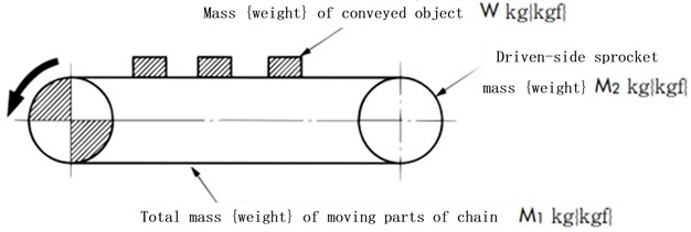
- M = Mass of moving parts (weight): Mass of chain *, bucket, apron, etc. (kg/m {kgf/m})
- W = Maximum total mass {weight} of the items being transported on the conveyor: kg {kgf}
For bulk items: W = C loading interval × amount of transported material {weight} - kW = required power
- f 1 = coefficient of friction between the chain and guide channel (Table 3)
- η = mechanical efficiency of the drive
- G = gravitational acceleration: 9.80665m/s 2
*When using two chains in parallel, the weight will be that of two chains.
*If forward and reverse operation is performed frequently, the chain will need to be taken up by take-up, so the calculation formula will differ from the one below.
If you are taking up slack in the chain with a take-up, please use the calculation formula in Q&A6 here.
Table 3-1 f 1: Friction coefficient when the rollers of the main chain roll on the rail
| Roller classification |
Steel roller | lambda chain |
Plastic Roller Injection | Low noise Plastic Roller |
Needle bushing chain |
|
|---|---|---|---|---|---|---|
| Lubrication (none) | Lubrication (with) | Lubrication (none) | Lubrication (none) | |||
| R Roller | 0.12 | 0.08 | 0.08 | 0.08 | 0.1 | 0.21 |
| S Roller | 0.21 | 0.14 | 0.14 | - | - | - |
Note) Plastic Roller include KV specifications.
Table 3-2 f 1: Friction coefficient when the chain plates slide on the rail
| Steel plate | Poly-steel chain | |
|---|---|---|
| Lubrication (none) | Lubrication (with) | |
| 0.3 | 0.2 | 0.25 |
calculation formula
| SI units | {gravity unit} |
|---|---|
|
Horizontal conveyance When carrying items F = (W + 2.1 × M × C) × f1 × G 1000 kW = F × V 6120 × 1 η 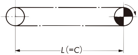
F = (W + 2.1 × M × C) × f1 kW = F × V 6120 × 1 η |
|
|
Vertical Conveyance F = (W + M × C) × G 1000 kW = W × V 60 × G 1000 × 1 η 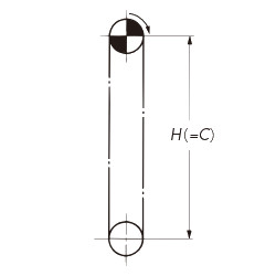
F = W + M × C kW = W × V 6120 × 1 η |
|
|
Inclined transport * When carrying items 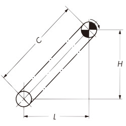
F = (W + M × C) L × f1 + H C + 1.1 × M × (L × f1 - H) × G 1000 kW = V 60 F - M × (H - L × f1) G 1000 × 1 η F = (W + M × C) L × f1 + H C + 1.1 × M × (L × f1 - H) kW = V 6120 F - M × (H - L × f1) × 1 η Note) In the formula for F marked with an asterisk, if L × f1- H < 0, then L × f1- H = 0. Also, in the formula for kW, if H - L × f1 < 0, then H - L × f1 = 0. |
|
|
Horizontal/inclined transport * When carrying items 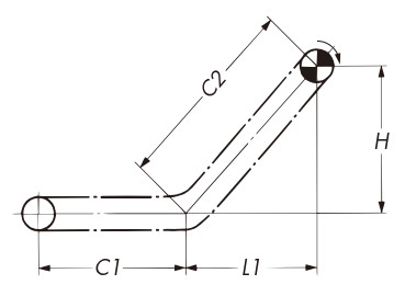
F =
(
W
C1 + C2
+ 2.1 × M) C1 × f1+
(
W
C1 + C2
+ M) × (L1 × f1 + H)
kW = V 60 F - M × (H - L1 × f1) G 1000 × 1 η F =
(
W
C1 + C2
+ 2.1 × M) × C1 × f1+
(
W
C1 + C2
+ M) × (L1 × f1 + H)
kW = V 6120 F - M × (H - L1 × f1) × 1 η Note) In the formula for F marked with an asterisk, if L 1 × f 1- H < 0, then L 1 × f 1- H = 0. Also, in the formula for kW, if HL 1 × f 1 < 0, then H - L 1 × f 1 = 0. |
|
Step 5. Determine the chain size
Multiply the maximum tension (F) acting on the chain by the speed factor (KV) from Table 4 to select a chain that satisfies the following formula.
F × K V ≦ Maximum allowable load
Table 4 Velocity coefficient (K V)
| Chain speed m/min | Velocity Factor (Kv) |
|---|---|
| 15 or less | 1.0 |
| 15~30 | 1.2 |
| 30~50 | 1.4 |
| 50~70 | 1.6 |
| 70~90 | 2.2 |
| 90~110 | 2.8 |
| 110~120 | 3.2 |
Recommended speeds for the chains listed below are:
|
30m/min以下 |
|
70m/min以下 |
Table 5: Strength of Small size conveyor chain (unit: kN{kgf})

| Size | General-purpose chain | Lambda Chain Long-life Lambda Chain |
|---|---|---|
| RF2040 | 2.65 {270} | 2.65 {270} |
| RF2050 | 4.31 {440} | 4.31 {440} |
| RF2060 | 6.28 {640} | 6.28 {640} |
| RF2080 | 10.7 {1090} | 10.7 {1090} |
| RF2100 | 17.1 {1740} | 17.1 {1740} |
| RF2120 | 23.9 {2440} | 23.9 {2440} |
| RF2160 | 40.9 {4170} | - |
| Size | Stainless steel Double pitch | Coated Double pitch | |||||
|---|---|---|---|---|---|---|---|
| SS Series | HS Series | AS Series | NS Series | LSK specifications | NP Series | NEP Series | |
| RF2040 | 0.69 {70} | 1.19 {121} | 0.69 {70} | 0.44 {45} | 0.44 {45} | 2.65 {270} | 2.65 {270} |
| RF2050 | 1.03 {105} | 1.85 {189} | 1.03 {105} | 0.69 {70} | 0.69 {70} | 4.31 {440} | 4.31 {440} |
| RF2060 | 1.57 {160} | 2.78 {283} | 1.57 {160} | 1.03 {105} | 1.03 {105} | 6.28 {640} | 6.28 {640} |
| RF2080 | 2.65 {270} | 4.77 {486} | 2.65 {270} | 1.77 {180} | - | 10.7 {1090} | 10.7 {1090} |
| RF2100 | 2.55 {260} | - | - | - | - | 17.1 {1740} | 17.1 {1740} |
| RF2120 | 3.82 {390} | - | - | - | - | 23.9 {2440} | - |
| RF2160 | 6.37 {650} | - | - | - | - | 40.9 {4170} | - |
| Size | General-purpose series | Low Noise Series | Heat-resistant specifications | |||||
|---|---|---|---|---|---|---|---|---|
| Standard Series | NP Series | SS Series | SP Roller | Standard Series | NP Series | SS Series | ||
| RF2040 | 0.44 {45} | 0.44 {45} | 0.44 {45} | 0.23 {23} | 0.44 {45} | 0.44 {45} | 0.44 {45} | 0.44 {45} |
| RF2050 | 0.69 {70} | 0.69 {70} | 0.69 {70} | 0.34 {34} | 0.69 {70} | 0.69 {70} | 0.69 {70} | 0.69 {70} |
| RF2060 | 1.03 {105} | 1.03 {105} | 1.03 {105} | 0.54 {55} | 1.03 {105} | 1.03 {105} | 1.03 {105} | 1.03 {105} |
| RF2080 | 1.77 {180} | 1.77 {180} | 1.77 {180} | 0.88 {89} | 1.77 {180} | 1.77 {180} | 1.77 {180} | - |
| RF2100 | 2.55 {260} | 2.55 {260} | 2.55 {260} | - | - | - | - | - |
| Size | General-purpose specifications | LMC specifications | NP Series | SS Series |
|---|---|---|---|---|
| RF2040 | 1.77 {180} | 1.47 {150} | 1.77 {180} | 0.44 {45} |
| RF2050 | 3.14 {320} | 2.55 {260} | 3.14 {320} | 0.69 {70} |
| RF2060 | 4.22 {430} | 3.43 {350} | 4.22 {430} | 1.03 {105} |
| RF2080 | 7.65 {780} | 6.18 {630} | 7.65 {780} | 1.77 {180} |
| Size | General-purpose specifications |
|---|---|
| RF2040 | 1.86 {190} |
| RF2050 | 2.84 {290} |
| RF2060 | 4.02 {410} |
| RF2080 | 6.96 {710} |
Indexing conveyor chain
| Size | Standard Series | High precision specifications | Stainless steel specifications |
|---|---|---|---|
| RF2040 | 0.78 {80} | 0.78 {80} | 0.44 {45} |
| RF2050 | 1.27 {130} | 1.27 {130} | 0.69 {70} |
| RF2060 | 1.77 {180} | 1.77 {180} | 1.03 {105} |
| RF2080 | 2.94 {300} | 2.94 {300} | 1.77 {180} |
| Size | Maximum allowable load |
|---|---|
| RF2040 | 0.45 {45} |
| RF2050 | 0.69 {70} |
| RF2060 | 1.03 {105} |
| RF2080 | 1.77 {180} |
| Size | Maximum allowable load |
|---|---|
| BCM12.5-9 | 0.3 {30} |
| BCM15-9 | 0.3 {30} |
| Size | Maximum allowable load |
|---|---|
| BC050 | 0.49 {50} |
| BC075 | 0.69 {70} |
| BC100 | 0.69 {70} |
| BC150 | 1.27 {130} |
| Size | General-purpose chain | Lambda Chain | Long Life Lambda Chain |
|---|---|---|---|
| RS25 | 0.64 {65} | - | - |
| RS35 | 1.52 {155} | 1.52 {155} | - |
| RS40 | 2.65 {270} | 2.65 {270} | 2.65 {270} |
| RS50 | 4.31 {440} | 4.31 {440} | 4.31 {440} |
| RS60 | 6.28 {640} | 6.28 {640} | 6.28 {640} |
| RS80 | 10.7 {1090} | 10.7 {1090} | 10.7 {1090} |
| RS100 | 17.1 {1740} | 17.1 {1740} | 17.1 {1740} |
| RS120 | 23.9 {2440} | 23.9 {2440} | - |
| RS140 | 32.4 {3300} | 32.4 {3300} | - |
| RS160 | 40.9 {4170} | - | - |
| Size | RS Attachment Chains | Coated RS Attachment Chains | Poly-steel chain | Plastic Roller chain |
|||||
|---|---|---|---|---|---|---|---|---|---|
| SS Series | HS Series | AS Series | NS Series | LSK specifications (Stainless steel roller) |
NP Series | NEP Series | SP Roller | ||
| RS25 | 0.12 {12} | - | - | 0.12 {12} | - | 0.64 {65} | - | 0.08 {8} | - |
| RS35 | 0.26 {27} | - | - | 0.26 {27} | - | 1.52 {155} | - | 0.18 {18} | - |
| RS40 | 0.69 {70} | 1.19 {121} | 0.69 {70} | 0.44 {45} | 0.44 {045} | 2.65 {270} | 2.65 {270} | 0.44 {45} | 0.23 {23} |
| RS50 | 1.03 {105} | 1.85 {189} | 1.03 {105} | 0.69 {70} | 0.69 {070} | 4.31 {440} | 4.31 {440} | 0.69 {70} | 0.34 {34} |
| RS60 | 1.57 {160} | 2.78 {283} | 1.57 {160} | 1.03 {105} | 1.03 {105} | 6.28 {640} | 6.28 {640} | 0.88 {90} | 0.54 {55} |
| RS80 | 2.65 {270} | 4.77 {486} | 2.65 {270} | 1.77 {180} | - | 10.7 {1090} | 10.7 {1090} | - | 0.88 {89} |
| RS100 | 3.82 {390} | - | - | - | - | 17.1 {1740} | 17.1 {1740} | - | - |
| RS120 | 3.82 {390} | - | - | - | - | 23.9 {2440} | - | - | - |
| RS140 | 4.61 {470} | - | - | - | - | 32.4 {3300} | - | - | - |
| RS160 | 6.37 {650} | - | - | - | - | 40.9 {4170} | - | - | - |
| Size | General-purpose specifications | Lambda Specification | NP Series | SS Series |
|---|---|---|---|---|
| RS40 | 1.77 {180} | 1.47 {150} | 1.77 {180} | 0.44 {45} |
| RS50 | 3.14 {320} | 2.55 {260} | 3.14 {320} | 0.69 {70} |
| RS60 | 4.22 {430} | 3.43 {350} | 4.22 {430} | 1.03 {105} |
| RS80 | 7.65 {780} | 6.18 {630} | 7.65 {780} | 1.77 {180} |
| Size | General-purpose specifications |
|---|---|
| RS40 | 1.86 {190} |
| RS50 | 2.84 {290} |
| RS60 | 4.02 {410} |
| RS80 | 6.96 {710} |
Note)
- 1. SS Series and NS Series are not oiled before shipping. When using in environments other than underwater or where it is exposed to water, please be sure to oil it before use.
- 2. If the chain is used without oiling, it may begin to bend poorly early.
- 3. Maximum allowable load is the value under oiled conditions (including water lubrication).
Step 6. Chain selection for intermittent operation
When using a chain for intermittent operation, such as with an indexing device, the tension acting on the chain must be taken into account not only in the selection of a general chain (tension F based on frictional force), but also in the additional tension F1 due to inertia.
The added tension F1 is generally calculated by F1 = mα. The calculation procedure is explained based on this formula.
- m = total mass of the driven side (kg)
- α = maximum acceleration (m/s 2)
| SI units | {gravity unit} | ||||||||
|---|---|---|---|---|---|---|---|---|---|
|
|||||||||
|
1) Calculate the total mass m of the driven side. m = W + M1 + 1 2 M2 Note) 1 2 M 2: Approximate value obtained by converting the inertia force of the sprocket into that of the chain. |
|||||||||
|
2) Using the maximum acceleration α (m/s 2) and the above formula, calculate the additional tension due to inertia as F1=mα. For example, when a cam-type indexing device is used, the maximum acceleration α is
Use the Am value that corresponds to the cam curve.
For details, please check with the indexing manufacturer. |
|||||||||
|
3) Calculate the total applied tension F Σ, taking into account the additional tension due to inertia. FΣ = F + F1/1000 F: Chain tension based on friction force (kN) 3) Calculate the total applied tension F Σ, taking into account the additional tension due to inertia. FΣ = F + F1/G F: Chain tension based on friction force (kN) G: Gravitational acceleration 9.80665 (m/s 2) |
|||||||||
|
4) Determine chain size F Σ Kv ≦ Maximum allowable load Kv: velocity coefficient (Table 4) |
|||||||||
|
5) Also check the allowable load on the chain rollers. ×
(You can move it by dragging it)
This is a guideline value that does not cause roller rotation problems, assuming use in a lubricated state. |
|||||||||

