technical data Large size conveyor chain Selection
10. Selection example
10.1 Bearing Roller Conveyor Chain
Selection is made for both Bearing Roller Conveyor Chain and DT Series conveyor chain.
1) Number of chain links required
n = 50000 250 × 2 + 12 × 2 = 412 × 2 = 824 links
2) Check the roller load
Effective number of rollers = Length of conveyed object Chain pitch = 1000 250 = 4
Since there are two chains, there are eight in total, but considering the uneven load, only four are effective.
Roller load = 2000 × g 1000 × 1 4 = 4.9 kN {500 kgf}/unit
From Table 11, Bearing Roller Conveyor Chain is RF12250BF-1LA2 - allowable load 5.49kN {560kgf}
The RF type conveyor chain available is RF26250F-DT-1LA2 - allowable load 5.30kN {540kgf}.
3) Check the allowable load mass on the conveyor
For the sake of simplicity, if we ignore the impact force at startup and the tensile force due to its own weight, the result is 2000 kg x 40 pieces/2 lines = 40,000 kg/line.
As shown in the table on the right, the bearing conveyor chain can be selected for the RF 10 ton size - 53,300 kg, and the conveyor chain can be selected for the RF 17 ton size - 44,600 kg.
When comparing the roller allowable load and the load mass, the roller allowable load takes priority.
This is a guideline value that assumes use in a lubricated state and does not cause roller rotation problems or early wear. Depending on the operating conditions (high speed, heavy load, long-term operation) and expected lifespan, select with a margin of error relative to the allowable value.
This is a guideline value that assumes use in a lubricated state and does not cause roller rotation problems or early wear. Depending on the operating conditions (high speed, heavy load, long-term operation) and expected lifespan, select with a margin of error relative to the allowable value.
Bearing Roller Conveyor Chain (f1=0.03)
T = 2000kg × g 1000 × 40 pieces × 0.03 = 23.5kN{2400kgf}
Conveyor chain (f1=0.08)
T = 2000kg × g 1000 × 40 pieces × 0.08 = 62.8kN{6400kgf}
Bearing Roller Conveyor Chain

Conveyor Chain

4) Motor size selection (dynamic loss is assumed to be 10%)
Motor kW = T × V 60 × 1.1 × 1 η = (η = 0.85)
Bearing Roller Conveyor Chain power requirement
kW = 23.5 × 10 60 × 1.1 × 1 0.85 = 5.1kW
Conveyor chain power
kW = 62.8 × 10 60 × 1.1 × 1 0.85 = 13.5kW
Allowable load mass quick reference table
| Conveyor Chain size |
Conveyor Chain (DT) | bearing roller Conveyor Chain (DT) |
|---|---|---|
| RF03 | 5400 | 14000 |
| RF05 | 12500 | 33300 |
| RF08・450 | 14300 | 36700 |
| RF10 | 20500 | 53300 |
| RF12 | 33900 | 90000 |
| RF17 | 44600 | 116700 |
| RF26 | 57100 | 150000 |
| RF36 | 86600 | 230000 |
| RF60 | 91100 | - |
| RF90 | 143800 | - |
| RF120 | 201800 | - |
Note) Friction coefficient for horizontal conveyor: [Conveyor chain: 0.08/Bearing roller: 0.03]
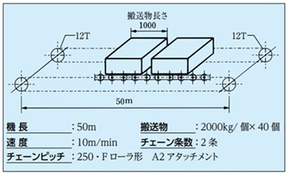
10.2 Conveyor type: Slat conveyor (horizontal)
- Transported items: box-shaped luggage
- conveyor length: 30m
- Load capacity: 1 item per 1m of transported goods
- Sprocket used: 12T
- Chain used: Pitch 100, F roller type chain with each link A2
- Usage time: 8 hours/day
- Slat weight: 10kg/sheet
- Number of chain threads: 2
- Transported material amount: 100 kg/piece
- Chain speed: 15m/min
- Usage environment: normal temperature
1) Number of chain links required: n
n = 30000 100 × 2 + 12 × 2 = 612 × 2 = 1224 links
2) Chain size
There are 30 objects on the conveyor. The total load mass on the conveyor is 100 x 30 = 3000 kg. The coefficient of friction is assumed to be 0.08 from Table 5, assuming lubrication.
The force T1 required to move only the transported object is
T 1 = 3000 ×
g
1000
× 0.08 = 2.35kN {T 1 = 3000 × 0.08 = 240kgf}
Next, the slat mass is 10 kg per slat and the pitch is 100, so slat mass = 10 × 1000 100 = 100 kg/m.
The force T2 required to move only the slat is
T 2 = 2.1 × 100 × 30 ×
g
1000
× 0.08 = 4.94kN {T 2 = 2.1 × 100 × 30 × 0.08 = 504kgf}
T 1 + T 2 = 2.35 + 4.94 = 7.29kN {T 1 + T 2 = 240 + 504 = 744kgf}
Maximum allowable load of two strands of RF03100F-DT is 4.20kN x 2 strands = 8.40kN {860kgf}, so it seems usable.
This is the limit value, assuming use in a lubricated state, taking fatigue, damage, and wear into consideration. If you calculate the correct chain tension based on the selection listed in our catalog and use it below this value, early failures will not occur. However, this does not include cases where performance degradation occurs in special environments.
If the chain size is RF03100F-DT-1LA2, the force T3 required to move only the chain is:
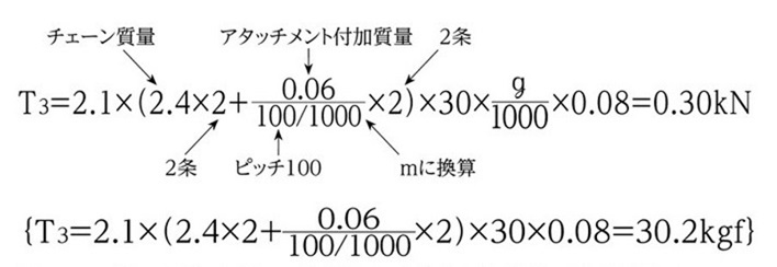
TMAX = T1 + T2 + T3 = 2.35 + 4.94 + 0.30 = 7.59kN
{TMAX = T1 + T2 + T3 = 240 + 504 + 30.2 = 774kgf}
Assuming that the load acting on the two chains is uniform, the corrected chain tension T' MAX of one chain
T' MAX = 7.59/2 pieces × K v × K T × K s = 7.59/2 × 1.0 × 1.0 × 1.0 = 3.80kN
RF03100F-1LA2 Maximum allowable load of a single wire is 4.20kN, so T' MAX = 3.80kN < 4.20kN
This is the limit value, assuming use in a lubricated state, taking fatigue, damage, and wear into consideration. If you calculate the correct chain tension based on the selection listed in our catalog and use it below this value, early failures will not occur. However, this does not include cases where performance degradation occurs in special environments.
The allowable roller load and allowable attachment load must satisfy Tables 10 and 11.
This is a guideline value that assumes use in a lubricated state and does not cause roller rotation problems or early wear. Depending on the operating conditions (high speed, heavy load, long-term operation) and expected lifespan, select with a margin of error relative to the allowable value.
This is the allowable vertical load for the A-type attachment. If a K-type attachment is used, calculate using twice the allowable load for the A-type attachment. Depending on the shape and structure of the attachment you install, a twisting force may be generated on the A-type attachment, so please contact us if you have any concerns.

3) Drive sprocket torque: Tr
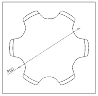
The pitch diameter of a sprocket with a pitch of 100 and N = 12T is Φ386.4
Tr = 7.59 × 386.4 × 1 2 × 1 1000 = 1.47kN・m
{Tr = 774 × 386.4 × 1 2 × 1 1000 = 149.5kgf・m}
4) Required power
kW = 7.59×15 60 × 1.1 × 1 0.85 = 2.46kW
{kW = 774 × 15 102 × 60 × 1.1 × 1 0.85 = 2.46kW}
10.3 Conveyor type: Continuous bucket elevator (vertical)
- Lifting height: 30m
- Chain used: Pitch 250, GA4 attachment every 2 links
(For S-roller bucket elevators) - Conveying capacity: 90t/h
- Bucket weight: 25 kg/piece
- Sprocket used: N = 12T
- Usage environment: normal temperature
- Usage time: 8 hours/day
- Chain speed: 28m/min
- Lubrication: Unlubricated
- Formation: Left and right mirror Image
1) Number of chain links required: n
n = 30000 250 × 2 + 12 × 2 = 252 × 2 = 504 links
2) Chain size
(1) Tension T1 due to the transported object only
T1 = 16.7 × 90 28 × (30 + 1) × g 1000 = 16.3kN
{T1 = 16.7 × 90 28 × (30 + 1) = 1664kgf}
Part: Add 1m to the center distance of the sprockets to account for the increased load when carrying objects. (See Vertical Transport for calculating the tension acting on the chain.)
(2) Tension due to bucket only T 2
With a chain pitch of 250, buckets are attached every two links, so the bucket mass is 25 kg x 2 = 50 kg/m.
T2= 50 × g 1000 × (30 + 1) = 15.2kN
{T2= 50 × (30 + 1) = 1550kgf}
(3) T1 + T2 = 16.3 + 15.2 = 31.5kN
{T1 + T2 = 1664 + 1550 = 3214kgf}
Here, B17250S (Maximum allowable load 35kN) is tentatively selected as the chain that can satisfy Maximum allowable load with two chains.
This is the limit value, assuming use in a lubricated state, taking fatigue, damage, and wear into consideration. If you calculate the correct chain tension based on the selection listed in our catalog and use it below this value, early failures will not occur. However, this does not include cases where performance degradation occurs in special environments.
B17250S The chain mass for every 2 links with the GA4 attachment is 15kg/m.
Article 2
↓
T3 = 15 × 2 × (30 + 1) × g 1000 = 9.12kN
{T3 = 15 × 2 × (30 + 1) = 930kgf}
(4) Assuming that the load imbalance between the left and right chains is 6:4, the chain tension TMAX of one chain is
16.3 × 0.6 + 15.2 2 + 9.12 2 = 21.9kN
{1664 × 0.6 + 1550 2 + 930 2 = 2238kgf}
Since it is lubricant-free, a margin of 1.5 is expected, taking into consideration wear life.
Correction chain tension T' MAX = 21.9 × Kv × KT × Ks × 1.5 = 21.9 × 1.05 × 1.0 × 1.0 × 1.5 = 34.5kN
{T'MAX = 2238 × 1.05 × 1.0 × 1.0 × 1.5 = 3524kgf}
From the above, the result is B17250S-CT-2LGA4.

Note: The inter-row load offset varies depending on the transport conditions, so please use a value that suits your actual usage conditions.
3) Drive sprocket torque: Tr
In the case of a vertical bucket elevator, the chain mass and bucket mass are balanced. Therefore, the only tension related to torque and required power is the tension T1 due to the transported object.
When the pitch is 250 and N = 12T, the pitch circle diameter is Φ965.9.
The diameter of the circle circumscribing the sprocket tooth pitch.
(JIS B 1812:2015)
Tr = 18.1 × 965.9 × 1 2 × 1 1000 = 8.74kN・m
{Tr = 1849 × 965.9 × 1 2 × 1 1000 = 893kgf・m}
4) Required power: Tr
kW = 18.1 × 28 60 × 1.1 × 1 0.85 = 10.9kW
{kW = 1849 × 28 102 × 60 × 1.1 × 1 0.85 = 10.9kW}

