technical data Drive chain Roller Chain Selection
5. General selection method
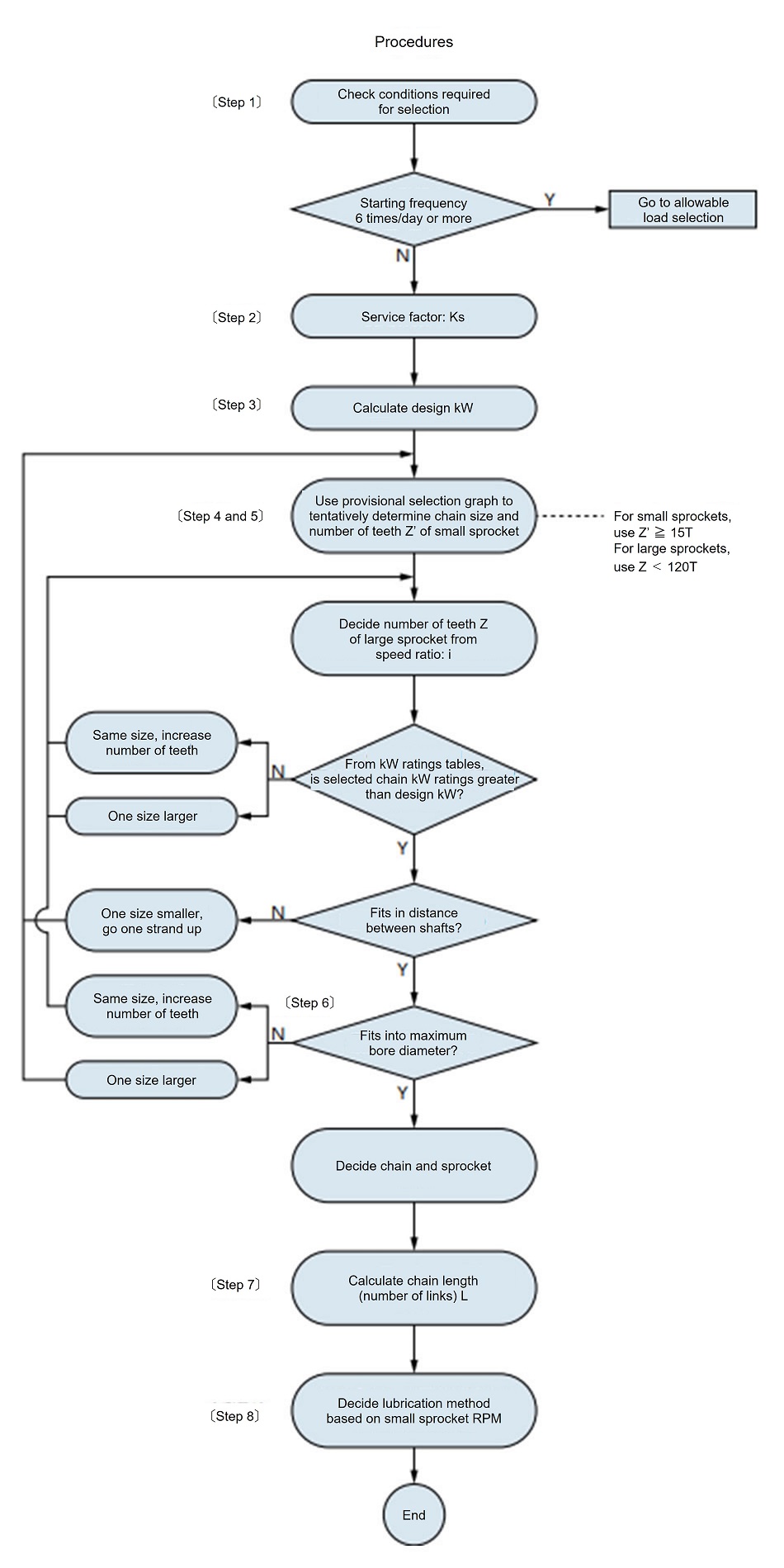
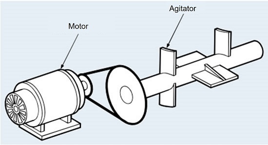
Winding transmission (forward and reverse) continuous rotation transmission
Steps 4 and 5: Selecting the chain and number of teeth on the small sprocket
Use the simple selection chart (here) or kW ratings table to determine the number of teeth on the chain and small sprocket that satisfies the rotational speed of the high-speed shaft and the required power transmission kW.
In this case, select a chain with the minimum pitch that has the required power transmission capacity.
If single strand chain is not powerful enough, choose multiple strand chain. Also, if there are restrictions on the location of use, the distance between the axes should be as short as possible.
When reducing the sprocket outer diameter, use multiple strand rollers with small pitch.
Please use a chain.
Step 6: Select the number of teeth on the large sprocket
Once the number of teeth on the small sprocket is determined, multiply it by the speed ratio to determine the number of teeth on the large sprocket.
The small sprocket should have at least 15 teeth, but it is not advisable for the large sprocket to have more than 120 teeth.
In this case, the number of teeth on the small sprocket will be reduced, but even in this case, we recommend using one with 13 or more teeth.
Step 7: Odd number of links
If there is an odd number of links, try to avoid using offset links as much as possible and change the center distance to make it an even number of links.
When using RS roller chain 's 1-pitch offset links or Super chain 's 4-pitch offset links, please allow for a reduction in power transmission capacity according to the notes in each kW ratings table.
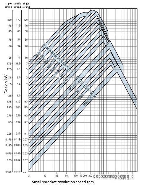
Simple selection diagram
How to read the diagram (Figure 2)
(Example) Correction kW = 7kW, single strand chain
- 1. When the small sprocket rotation speed is 100 r/min
Looking at design kW = 7kW (vertical axis) and the rotational speed (horizontal axis), the chain is RS80 and the sprocket is smaller than 18T but larger than 13T, so we can determine that a sprocket with a size of around 15T (15 teeth) can be used based on the intersection position. - 2. When the small sprocket rotation speed is 200 r/min
Using the same method as the previous example, it would be determined to be smaller than RS60-18T and larger than RS60-13T. After making a rough selection using this table, confirm it using the kW ratings table by chain number. - 3. When using 1-pitch offset links or Super chain 4-pitch offset links, allow for a reduction in power transmission capacity according to the notes in each kW ratings table.
Figure 2: RS roller chain simple selection chart
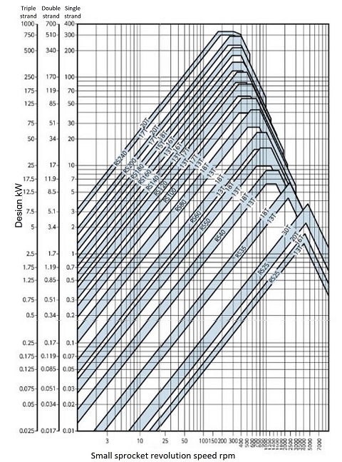
Figure 3 Simple selection diagram for RS-HT RS-HT chain
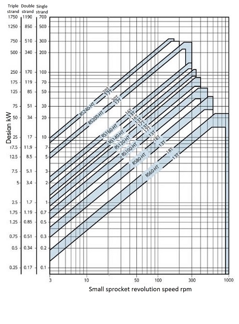
Figure 4 Super chain RS-SUP simple selection diagram
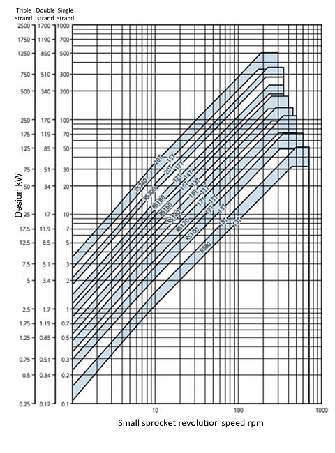
Fig. 5. RS roller chain BS/DIN standard Simple Selection Chart
Simple selection diagram
How to read the diagram (Figure 2)
(Example) Correction kW = 7kW, single strand chain
- 1. When the small sprocket rotation speed is 100 r/min
Looking at design kW = 7kW (vertical axis) and the rotational speed (horizontal axis), the chain is RS80 and the sprocket is smaller than 18T but larger than 13T, so we can determine that a sprocket with a size of around 15T (15 teeth) can be used based on the intersection position. - 2. When the small sprocket rotation speed is 200 r/min
Using the same method as the previous example, it would be determined to be smaller than RS60-18T and larger than RS60-13T. After making a rough selection using this table, confirm it using the kW ratings table by chain number. - 3. When using 1-pitch offset links or Super chain 4-pitch offset links, allow for a reduction in power transmission capacity according to the notes in each kW ratings table.
Figure 2: RS roller chain simple selection chart
Figure 3 Simple selection diagram for RS-HT RS-HT chain
Figure 4 Super chain RS-SUP simple selection diagram
Fig. 5. RS roller chain BS/DIN standard Simple Selection Chart
Service factor Ks
The transmission capacity is based on the condition that the load fluctuation is small, so the transmission kW is corrected by Service factor Ks depending on the size of the load fluctuation.
Service factor Ks is determined based on Table 2, depending on the type of machine and prime mover.
Multiply the transmitted kW by Service factor to find design kW.
| Shock type | Examples of machines used | Type of engine | ||
|---|---|---|---|---|
| motor turbine |
Internal Combustion Engines | |||
| Fluid Coupling Attached |
Fluid Coupling none |
|||
| Smooth transmission | Belt conveyors and chain conveyors with minimal load fluctuations Centrifugal pumps, centrifugal blowers, general textile machinery, General machinery with little load fluctuation |
1.0 | 1.0 | 1.2 |
| A bit of a shock Accompanying transmission |
Centrifugal compressors, marine propulsion units, conveyors with slight load fluctuations, Automatic furnaces, dryers, crushers, general machine tools, compressors, General construction machinery, general paper-making machinery |
1.3 | 1.2 | 1.4 |
| A big shock Accompanying transmission |
Presses, crushers, construction and mining machinery, vibrating machines, Oil well drills, rubber mixers, rolls, roll guns, General machinery subject to reverse or shock loads |
1.5 | 1.4 | 1.7 |
Selection example using the general selection method
Step 1: Selection requirements
- Machine used: Mixer
- Shock type: Moderate shock
- Prime mover type: Motor
- Rated power: 11kW 1800 r/min
- High-speed shaft: Shaft hole diameter Φ45 90 r/min
- Low speed shaft: Shaft hole diameter Φ60 30 r/min
- Center distance: 350mm
- Other: Space between axes: 700mm
Step 2: Determine Service factor
Service factor Table 2, Service factor Ks = 1.3
| Shock type | Examples of machines used | Type of engine | ||
|---|---|---|---|---|
| motor turbine |
Internal Combustion Engines | |||
| Fluid Coupling Attached |
Fluid Coupling none |
|||
| Smooth transmission | Belt conveyors and chain conveyors with minimal load fluctuations Centrifugal pumps, centrifugal blowers, general textile machinery, General machinery with little load fluctuation |
1.0 | 1.0 | 1.2 |
| A bit of a shock Accompanying transmission |
Centrifugal compressors, marine propulsion units, conveyors with slight load fluctuations, Automatic furnaces, dryers, crushers, general machine tools, compressors, General construction machinery, general paper-making machinery |
1.3 | 1.2 | 1.4 |
| A big shock Accompanying transmission |
Presses, crushers, construction and mining machinery, vibrating machines, Oil well drills, rubber mixers, rolls, roll guns, General machinery subject to reverse or shock loads |
1.5 | 1.4 | 1.7 |
Step 3: Determine design kW
design kW = 11kW x 1.3 = 14.3kW
Steps 4 and 5: Selecting the chain and number of sprocket teeth
Based on the high-speed shaft rotation speed of 90 r/min and design kW (14.3 kW), calculate the chain number and the number of teeth on the small sprocket.
- (1) Using the simple selection chart (here) and kW ratings table, 17T for RS100-1 can be determined.
The speed ratio is 1/3, so the required number of teeth is 17T and 51T for the RS100.
However, the outer diameter of the sprockets is Φ189 for 17T and Φ534 for 51T, which are unsuitable as they do not fit into the required space.
∵ 189 + 534 > 700 - (2) So, when we look at multiple strand chains,
For a two-row setup, 19T and 57T RS80-2 are required, with sprocket outer diameters of Φ167 and Φ476, which are within the space limitations.
Check the 19T transmission capacity of this RS80-2 in the RS80 kW ratings table.
When the small sprocket has 19 teeth, the transmitted kW is 5.06kW at 50 r/min and 9.44kW at 100 r/min, so proportional calculations are made using the difference between these values. The transmitted kW at r/min is 8.56kW. - (3) This 8.56kW is the power transmission capacity of single strand chain. The power transmission capacity of the planned double-strand chain is calculated by multiplying it by multiple strand factor in Table 1.
8.56kW x 1.7 = 14.6kW×(You can move it by dragging it)multiple strand factor
The power transmission capacity of multiple strand roller chain cannot be expected to be No. of strands of that of single strand roller chain, because the load on each strand of the chain is not equally distributed.
Therefore, the power transmission capacity of multiple strand roller chain is calculated by multiplying the power transmission capacity of single strand roller chain by multiple strand factor.
Table 1 multiple strand factor No. of strands roller chain strands multiple strand factor 2 rows 1.7 3 rows 2.5 4 rows 3.3 5 rows 3.9 6 rows 4.6 - (4) This transmission capacity of 14.6 kW satisfies design kW (14.3 kW).
Step 6 Check the shaft hole diameter
Check the shaft hole diameter in the dimension table. The maximum shaft hole diameter for RS80-2-19T is Φ66, so it can be used for the required shaft hole diameter of Φ45.
The maximum shaft hole diameter of RS80-2-57T is Φ89, so Φ60 can be used.
Step 7: Determine the center distance
If the center distance is 350 mm,(167 + 476)2 < 350 fits in the requested space.
The number of links is calculated using the formula
When using a two-shaft winding transmission
- (1) When the center distance and number of teeth of both sprockets are fixed
L = Z + Z' 2 + 2C + Z - Z' 6.28 2 C
- (2) When the number of chain links and teeth is fixedC = 1 8 2L - Z - Z' + (2L - Z - Z')2 - 8 9.86 (Z - Z')2Any fractional part (decimal part) of the calculated L value will be rounded up and counted as one link, even if it is small.
If there is an odd number of links, an offset link must be used, but if possible, change the number of sprocket teeth or the center distance to make it an even number of links.
- L: Chain length (number of links)
- Z: Number of teeth on the large sprocket
- Z': Number of teeth on small sprocket
- C: Center distance expressed in number of links
L = 57 + 192 + 2 × 35025.4 + 57 - 196.28235025.4 = 68.2
To make it an even number of links, round up to 70 links.
Step 8 Check the lubrication type
The small sprocket is RS80-2-19T and has a rotation speed of 90 r/min, so according to kW ratings table, drip lubrication is required.
Note: Regarding the selection of roller chains for suspension and trolley drive applications
When using a balance weight, it is assumed that the motor capacity will be reduced and only the brake capacity will be increased.
In this case, for those indicated Maximum allowable load, also use the allowable tension selection method to select the chain, and select the roller chain with the greater margin.
Please also refer to the formula used for chain selection (here).

