technical data Cable Carrier (CABLEVEYOR)-Cable Carrier (CABLEVEYOR) Usage Limits
What is the lifespan of Cable Carrier (CABLEVEYOR)?
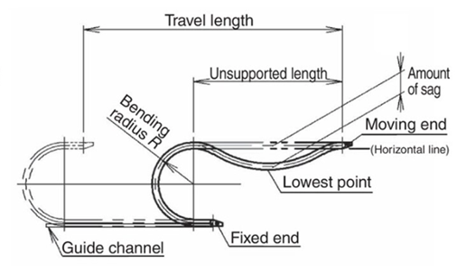
As Cable Carrier (CABLEVEYOR) operates (reciprocating), the pins and holes at the link connections wear out, and the no-back vent restrictor wears out, causing the free span section to sag (see diagram on the right).
The end of the life is determined when the cable/hose protection and stable behavior of Cable Carrier (CABLEVEYOR) and main body can no longer be ensured due to the impact.
The standard for judgment will be when the smaller of the following 1 or 2 is reached.
Limit value of deflection of free span section (guideline)
1. 10% of unsupported length
2. Cable Carrier (CABLEVEYOR) bending radius (R)
(example)
unsupported length:
500mm (⇒500mm x 0% = 50mm) → Limit deflection (approximate) 50mm
Cable Carrier (CABLEVEYOR) bending radius: R55
■If Cable Carrier (CABLEVEYOR) develops cracks, chips, or other damage due to aging, the Cable Carrier (CABLEVEYOR) is considered to have reached the end of its life.
Lifespan promoters
Cable Carrier (CABLEVEYOR) 's life may be shortened in the following cases:
- 1.High acceleration/deceleration speed and operating frequency.
- 2. Presence of wear inclusions such as dust.
- 3. Vibrations from outside.
- 4. Poor installation accuracy.
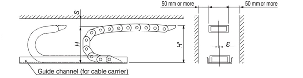
■ Cable Carrier (CABLEVEYOR) installation accuracy guidelines (recommended)
- - The misalignment (ε value) between the moving end and fixed end positions must be smaller than the allowable value.
- - The installation height (H' value) must be within the recommended value. (Note: Do not install at the total height (H value).)
- -Leeway space (S value) is larger than the recommended value.
- ・Provide guide channel (Cable Carrier (CABLEVEYOR) carriers)
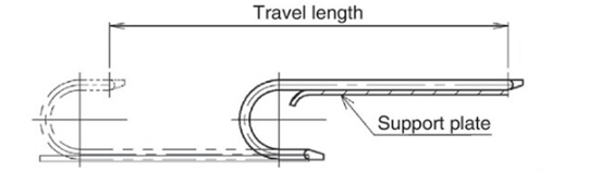
Cable Carrier (CABLEVEYOR) life extension measures
By installing support rollers or support plates from the beginning of operation to control the deflection of Cable Carrier (CABLEVEYOR), the life of Cable Carrier (CABLEVEYOR) itself can be extended.
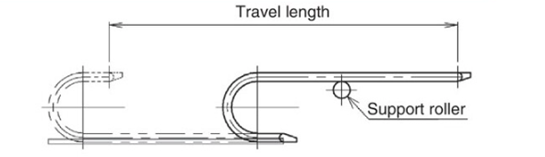
Note: When adding support rollers or support plates when the deflection of the free span section has progressed, the installation position (height) and, in the case of support plates, the shape (the part where the free span section moves onto the rail) must be set taking into account the amount of deflection of the free span section at that time.
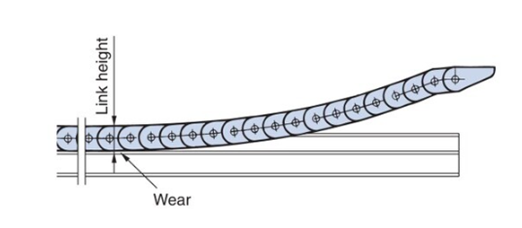
Gliding arrangement specification life expectancy
With Gliding arrangement specifications, the inner circumference of the link will wear over time. The guideline for replacement is when the wear amount of the link height (or the wear amount of sliding shoe if equipped with sliding shoe) reaches the allowable value (table on the right). For TKP58H39 with sliding shoe, TKP68H46 with sliding shoe, TKP91 (H56, H80), TKC91 (H56, H80), TKMK type, and TKMT type, only sliding shoe can be replaced. For information on the life extension effect of sliding shoe, please refer to Gliding arrangement specification page.
| Size | Allowable wear (mm) | |
|---|---|---|
| No sliding shoe | With sliding shoe shoe | |
| TKP35H22 | 1 | - |
| TKP45H25 | 1.5 | - |
| TKP58H39 | 1.5 | 5 |
| TKP62H34 | 1 | - |
| TKP68H46 | 1.5 | 5 |
| TKP90H50 | 1.5 | - |
| TKP125H74 | 1.5 | - |
| TKP91H56 | - | 7 |
| TKP91H80 | - | 7 |
| TKC34H25 | 1 | - |
| TKC47H36 | 1 | - |
| TKC64H50 | 1.5 | - |
| TKC85H68 | 1.5 | - |
| TKC91H56 | - | 7 |
| TKC91H80 | - | 7 |
| TKMK47H28/TKMT47H26 | - | 1.5 |
| TKMK65H42/TKMT65H38 | - | 1.5 |
| TKMK95H58/TKMT95H54 | - | 1.5 ※ |
| TKMK125H72/TKMT125H68 | - | 1.5 ※ |
*Larger values (different sliding shoe thickness) are also available. Please contact us if necessary.

