Cable Carrier (CABLEVEYOR) Plastic Series Special Specifications
Gliding arrangement
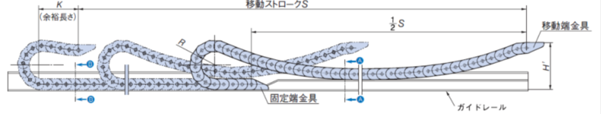
- This is a method of use in which Cable Carrier (CABLEVEYOR) slides on guide channel when a long stroke is required that exceeds the free span on Allowable load graph when two Cable Carrier (CABLEVEYOR) support rollers are installed.
Applicable Series: TKP Series, TKC Series, TKMK Series, TKMT Series

[Click to enlarge]
Note
If substances that accelerate wear, such as iron powder or dust, get into the sliding section, it may cause abnormal wear or buckling. Take measures to prevent such substances from accumulating on the rail or Cable Carrier (CABLEVEYOR) itself.
Gliding arrangement specification list
Please refer to the Gliding arrangement specification list for products that are compatible with Gliding arrangement specifications.
Usage precautions
*Please note the following points when using this product.
- ■Be sure to install guide channel.
- Our company's dedicated guide channel are convenient. If you are manufacturing your own rails, please refer to the diagram above.
- ■ Pay attention to the H' dimension.
- This differs from the H' dimension in the standard installation layout. Please install using the dimensions listed in the Gliding arrangement specification table. If this dimension is too high or too low, it may cause Cable Carrier (CABLEVEYOR) to buckle or lift up, resulting in damage to Cable Carrier (CABLEVEYOR).
- ■ Ensure there is sufficient Leeway length (K dimension).
- This differs from Leeway length in the standard installation layout. Set the number of links so that it is equal to or greater than the dimension listed in the Gliding arrangement specification table. If this dimension is too small, when the moving end is at the position where unsupported length is shortest, the link may be forced to bend in the opposite direction, which could damage Cable Carrier (CABLEVEYOR).
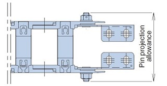
- ■ A special moving end bracket is required (excluding some model numbers).
- The special moving end fittings are designed to articulate in both directions. Also, only the TKP45H25 and TKP58H39 have pin projection dimensions that differ from the standard products.
| Size | Pin projection | |
|---|---|---|
| TKP45H26 | W38 | Inner width W+40 |
| Other than the above | Inner width W+42 | |
| TKP58H39 | Inner width W+45 | |
| TKP68H46 (when using mounting bracket) | Inner width W+46 | |
|
■Please use FOA for Fixed end bracket.
If Fixed end bracket is FIA or FIB, it cannot be used because Fixed end bracket Cable Carrier (CABLEVEYOR) as shown in the diagram below (center).
Also, in the case of FC, Fixed end bracket and guide channel come into contact as shown in the diagram below (right), so it cannot be used.

[Click to enlarge]
■ Be careful not to let the machine body come to the left of the moving end bracket.
If the machine body is located to the left of the moving end bracket, there is a risk of interference between the machine body and Cable Carrier (CABLEVEYOR) when Cable Carrier (CABLEVEYOR) travels to the left (see diagram below).

[Click to enlarge]
Gliding arrangement specification/ sliding shoe series
Gliding arrangement specification sliding shoe series contributes to reducing total costs and environmental impact by extending life with Long travel length and high-speed movement, saving labor, and reducing running costs.
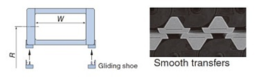
■Features 1. Longer lifespan
The use of a resin material with excellent sliding properties and abrasion resistance (flame retardant standard: equivalent to UL standard 94HB) and increased wear allowance (allowable wear amount) has resulted in a longer Cable Carrier (CABLEVEYOR) life.

[Click to enlarge]

[Click to enlarge]
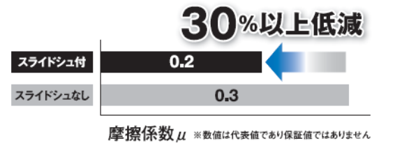
■Feature 2. Labor saving
The running resistance of Cable Carrier (CABLEVEYOR) is reduced, contributing to reduced power consumption on the machine side.
[Click to enlarge]
■Feature 3. Reduced running costs
When sliding shoe reaches the end of its wear life, as long as there is no damage to Cable Carrier (CABLEVEYOR) body, it can continue to be used by simply replacing sliding shoe.
Compared to when sliding shoe is not installed, the parts costs and labor required for replacement can be significantly reduced.
List of sliding shoe compatible products
| Variety | Size | Pitch | Inner Height | Inner width | bending radius | sliding shoe Installation |
|---|---|---|---|---|---|---|
| TKP Series | TKP58H39 | 58 | 39 | 50・75・100・125 | 75・90・125・150・200 | Option |
| TKP68H46 | 68 | 46 | 75・100・125・150・175 | 75・100・125・150・200・250 | Option | |
| TKP91H56 (Note | 91 | 56 | 150・175・200・225・250・275・300・325・350・400・450・500 | 200・250・300 | Essential | |
| TKP91H80 (Note | 91 | 80 | 150・175・200・225・250・275・300・325・350・400・450・500 | 200・250・300・350・400 | Essential | |
| TKMK Series | TKMK47H28 | 47.5 | 28 | 56・104・152・192 | 100・160・200 | Essential |
| TKMK65H42 | 65 | 42 | 66・106・154・194・258 | 95・115・145・220 | Essential | |
| TKMK95H58 | 95 | 58 | 114・162・210・258・306・402・514 | 140・170・200・290 | Essential | |
| TKMK125H72 | 125 | 72 | 151・247・359・407・455・503 | 180・220・260・340・380 | Essential | |
| TKC Series | TKC91H56 (Note | 91 | 56 | 150・200・250・300・350・400 | 200・250・300 | Essential |
| TKC91H80 (Note | 91 | 80 | 150・200・250・300・350・400 | 200・250・300・350・400 | Essential | |
| TKMT Series | TKMT47H26 | 47.5 | 26 | 56・80・104・152・192 | 100・160・200 | Essential |
| TKMT65H38 | 65 | 38.5 | 66・106・130・194・258 | 95・115・145・220 | Essential | |
| TKMT95H54 (Plastic cover type) |
95 | 54.5 | 114・130・162・258・306 | 140・170・200・290 | Essential | |
| TKMT125H68 | 125 | 68.5 | 135・183・247 | 220・260・340・380 | Essential |
Note) Fixed end bracket (plastic bracket) is also a special type (with sliding shoe).
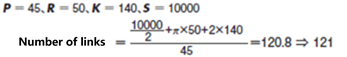
Calculation of number of links

*If the fixed end is in the center of the stroke, any decimal point will be rounded up to an integer.
■ Calculation example When using TKP45H25-30W58R50 with travel length of 10m.
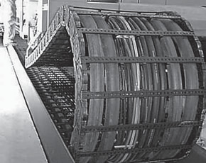
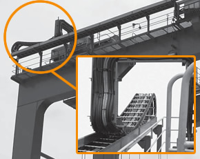
Gliding arrangement specification application example
Mobile trolley
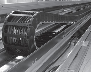
Cutting machine
crane
お問合せ先について
ホームページからのお問合せ
英語でのお問い合わせは、つばきグループホームページの問合せページを開きます。
If you are purchasing this product outside of Japan, please contact your nearest overseas office at the link below.

