technical data Cable Carrier (CABLEVEYOR)- Selecting Cable Carrier (CABLEVEYOR)- Selecting Cable Carrier (CABLEVEYOR) Steel Series
Selection of Cable Carrier (CABLEVEYOR) Series
For TK and TKH types
Size determined by cable/hose storage space
For TK and TKH types, the supporter hole (D) will be machined to your specified dimensions.
Calculate the minimum required width B' of the supporter based on the outer diameter and number of cables/hoses, and select a supporter with width B ≥ B'.
■ Supporter dimensions
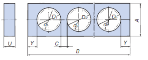
・Calculation of supporter hole diameter
D: Supporter hole diameter (integer value of Φ8 or more) d: Cable/hose outer diameter
・Calculation of the minimum required width of the supporter
B': Minimum required width of supporter C: 4mm or more Y: See table below
| Size | Y minimum |
|---|---|
| TK070 | 10 |
| TK095 | 15 |
| TK130 | 18 |
| TK180 | 18 |
| TKH250 | 25 |
*Please refer to each product page for supporter dimensions.
・Selection of supporters
Select A and B dimensions from the above calculation results and the supporter dimensions for each model.
Supporters are attached every two links starting from the second link on the moving end side.
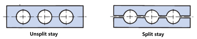
■ Integrated and split supporter types
The TK and TKH Cable Carrier (CABLEVEYOR) are available with two types of supporters: one-piece supporters and split supporters. Split supporters allow one side to be easily removed, making it easy to attach and remove supports. This is convenient for use with hoses with nozzles, when travel distance is long, or when there are many supported objects.
For TKS type
■ Frame
The number of partitions should be greater than or equal to the minimum required, and should be determined so that one cable or hose can fit into one hole whenever possible. When arranging the cables and hoses, also take into consideration the left and right mass balance.
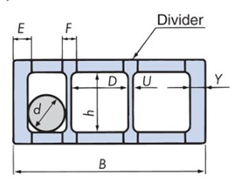
Calculate the minimum required frame width B' based on the outer diameter and number of cables and hoses, and select a supporter that satisfies frame width B ≥ B'.
・Calculation of required inner width
D: Required inner width (rounded up to the nearest whole number) d: Cable/hose outer diameter
・Calculating the minimum required frame width
B': Minimum required frame width U: Partition plate thickness Y: Link plate thickness
・Frame selection
Select the frame based on the above calculation results and frame dimension B for each model.
Quantity of frames and dividers
The frame is installed every two links.
Number of partitions (m) = n x (number of partitions in one location)
| Size | B | h | Y | U | E | F | Maximum cable/hose diameter d |
|---|---|---|---|---|---|---|---|
| TKS070 | 100 150 200 | 31 | 10 | 3 | 15 | 13 | 27 |
| TKS095 | 46 | 12 | 4 | 17 | 14 | 42 |
| Size | Minimum number of dividers required | ||
|---|---|---|---|
| B=100 | B=150 | B=200 | |
| TKS070 | 0 (5) | 1 (8) | 2 (12) |
| TKS095 | 0 (4) | 1 (7) | 2 (11) |
( ) indicates the maximum number that can be installed
bending radius R/strength selection
Selection based on Allowable load graph
travel length S on Allowable load graph applies when the fixed end of Cable Carrier (CABLEVEYOR) is installed at the center of travel length.
Please select the strength based on Allowable load graph of each model, taking into account travel length, cable/hose mass, cable/hose outer diameter, and allowable bending radius of the cable/hose.
Model selection example: When selecting the TKC model
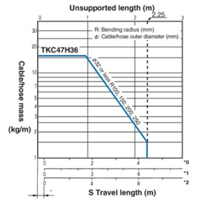
Usage conditions
travel length: 3m
Cable/hose mass: 4kg/m
Cable/hose outer diameter: Φ20mm (1 piece)
Allowable bending radius of cable/hose: 160 mm
Find the intersection of the horizontal axis (3m) and the vertical axis (4kg/m) in the table on the left, and select TKC47H36, which satisfies this point.
Allowable bending radius of cable/hose (r) < bending radius of Cable Carrier (CABLEVEYOR) (R)
R=200 that satisfies this condition is determined.
Therefore, based on the above conditions, the appropriate part would be TKC47H36W80R200.
Speed/acceleration confirmation
The allowable movement speeds for each product type and installation method are shown below. Please make sure that your operating conditions do not exceed the allowable values. (If they do, please contact us.)
| TKP | TKC | TKMK/ TKMT |
TKR | TKQ | TK | TKH | TKS | TKI | TKV | |
|---|---|---|---|---|---|---|---|---|---|---|
| Standard | 300 | 300 | 300 | 300 | 600 | 60 | 60 | 60 | 120 | 150 |
| Support Roller | 150 | 150 | 150 | 150 | 150 | 60 | 60 | 60 | - | - |
| Support plate | - | 60 | - | - | - | - | - | - | - | - |
| horizontal | 60 | 60 | 60 | - | - | 30 | 30 | 30 | - | - |
| U-shaped | 300 | 300 | 300 | 300 | 600 | 60 | 60 | - | - | - |
| inverted U-shape | 300 | 300 | 300 | 300 | 600 | 60 | 60 | - | - | - |
| Downward movement | 300 | 300 | 300 | 300 | 600 | 60 | 60 | 60 | - | - |
| combination | 300 | 300 | 300 | 300 | 600 | 60 | 60 | 60 | - | - |
| Gliding arrangement | * | * | * | - | - | - | - | - | - | - |
| Traveling roller | - | - | - | - | - | 30 | - | - | - | - |
| Vertical rotation | 60 | - | - | - | - | 60 | - | - | - | - |
| Horizontal rotation | 30 | 30 | - | - | - | 30 | - | - | - | - |
*Please refer to the catalog for Gliding arrangement specifications (marked with *).
*- indicates not applicable.
*Please contact us regarding the TKUA type.
| TKP | 2G |
|---|---|
| TKC | 3G |
| TKR | 2G |
| TKQ | 4G |
| TK | 1m/sec2 |
| TKS | 1m/sec2 |
| TKH | 1m/sec2 |
| TKI,TKV | 3G |
| TKMK,TKMT | Please contact us |
If the acceleration is very high, the life of the product may be shortened. Please make sure that the operating conditions do not exceed the values in the table above. (If they do, please contact us.)
- Reference - Comparison of bending radius and cross-sectional dimensions of TKMK and TKMT types
The open series and closed series have different bending radius and inner width dimensions, so please refer to the table below.
| Size | bending radius | Inner width dimensions | Inner height dimensions |
|---|---|---|---|
| TKMK47H28 | 55, 75, 100, 160, 200, 250 | 24, 56, - , 104, 152, 192 | 28 |
| TKMT47H26 | - , 75, 100, 160, 200, 250 | - , 56, 80, 104, 152, 192 | 26 |
| TKMK65H42 | 75, 95, 115, 145, 220, 300 | 66, 106, - , 154, 194, 258 | 42 |
| TKMT65H38 | - , 95, 115, 145, 220, 300 | 66, 106, 130, - , 194, 258 | 38.5 |
| TKMK95H58 | 140, 170, 200, 290, 380 | 114, - , 162, 210, 258, 306, 402, 514 | 58 |
| TKMT95H54 (Plastic cover type) | 140, 170, 200, 290, 380 | 114, 130, 162, - , 258, 306 | 54.5 |
| TKMT95H54 (Aluminum cover type) | 140, 170, 200, 290, 380 | 100 to 400 (every 1 mm) | 54.5 |
| TKMK125H72 | 180, 220, 260, 340, 380, 500 | - , 151, - , 247, 359, 407, 455, 503 | 72 |
| TKMT125H68 | - , 220, 260, 340, 380, 500 | 135, - , 183, 247 | 68.5 |

