technical data Synchronous Belts and Belt Sprockets Selection
Selection based on inertial load / Selection example
Items required for selection
The items required for selection are as follows. Please define the conditions for each.
- (1) In the case of a rotating body
Shape and dimensions of the rotating body, mass, rotation speed, acceleration (deceleration) time, shaft diameter, shaft distance, daily usage time, start-up frequency, speed ratio, whether or not an idler is used, and other conditions - (2) For linearly moving bodies
Pulley pitch circle diameter, mass of linear moving body, support method, friction coefficient of support mechanism, motion speed, acceleration (deceleration) time, shaft diameter, center distance, daily usage time, start frequency, speed ratio, whether or not an idler is used, and other conditions
Calculating the moment of inertia
The moment of inertia is calculated using the following formula:
- (1) In the case of a rotating body
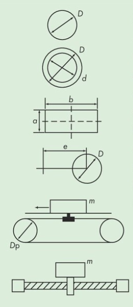
・Solid cylinder
I = 1 8 mD2・Hollow cylinder
I = 1 8 m (D2 + d2)・Rectangular cross section
I = 1 12 m (a2 + b2)Eccentric rotating body
I = 1 8 mD2 + me2 - (2) In the case of a linearly moving body
I = 1 4 mDp2
- (3) Ball screw drive
I = 1 4 m L π 2
- (4) Total moment of inertia
∑I = (I1 + I2 + ....)R2
*The moment of inertia of all moving bodies (including driven pulleys) driven by the belt is summed up using the formula on the left.
- I: Moment of inertia of each moving body kg・m 2
- ∑I: Total moment of inertia
- m: Mass of rotating or linearly moving body kg
- D: Outer diameter of rotor m
- d: Inner diameter of the hollow part of the rotor m
- a: length of the side of the rectangular cross section m
- b: length of the side of the rectangular cross section m
- e: Eccentricity distance m
- Dp: Pulley pitch circle diameter m
- L: Screw lead m
- R: Reduction ratio (number of teeth on the drive pulley/number of teeth on the driven pulley)
Calculation of acceleration (deceleration) torque
The acceleration (deceleration) torque is calculated using the following formula.
Pa = ∑I × (n2 - n1) 9.55 × ta
- Pa: Acceleration (deceleration) torque N・m
- n1: Rotational speed before acceleration (deceleration) r/min
- n2: Rotational speed after acceleration (deceleration) r/min
- ta: Acceleration (deceleration) time s
Calculating the continuous load torque
The continuous load torque is calculated using the following formula:
(1) Horizontal movement
Pc = 4.9 × mµDp
(2) Vertical movement
Pc = 4.9 × mDp
- Pc: Continuous load torque N・m
- μ: Friction coefficient of the moving body support mechanism
Determining the design torque
The design torque is calculated using the following formula. For Ko and Ka, use the values in the boxes below.
Pt = (Pa + Pc) × (Ko +Ki + Ks) × Ka × Ke※
Load correction factor
| Daily driving time h | <3 | 3~10 | 10< |
|---|---|---|---|
| Ko | 1.2 | 1.3 | 1.5 |
Start/stop frequency correction coefficient
| Number of starts and stops per day | ≦10 | 11~100 | 101~999 | 1000≦ |
|---|---|---|---|---|
| Ka | 1.1 | 1.2 | 1.3 | 1.5 |
- Pt: Design torque N・m
- Pa: Acceleration (deceleration) torque N・m
- Pc: Continuous load torque N・m
- Ko: Load correction coefficient (see table on the left)
- Ki: Correction factor when using an idler...Table 2
- Ks: Correction coefficient when speed increases...Table 3
- Ka: Start/stop frequency correction coefficient (left table)
- Ke: Operating atmosphere coefficient 1.2
*When using Ultra PX Belt HA specification (oil/water resistant) in an environment where it may be exposed to oil or water, or when using PX Belt water resistant specification in an environment where it may be exposed to water, multiply the operating atmosphere coefficient (Ke) by 1.2.
*From this point on, continue with the selection process from "Determining the belt size and number of pulley teeth."
sizing example (selection based on inertial load)
Items required for selection
The items required for selection are as follows:
| item | Content |
|---|---|
| (machine tool table drive) | |
| Pulley pitch diameter | 50mm or less |
| Mass of a linearly moving body | 50kg |
| Support method and friction coefficient of support mechanism | LM guide, friction coefficient μ=0.1 |
| movement speed | 1000r/min |
| Acceleration (deceleration) time | 0.3s |
| Shaft diameter | 20mm |
| Center distance | 1400mm |
| Daily usage time and startup frequency | 12 hours/day, 1000 times/day |
| speed ratio | 1:1 |
| Whether or not an idler is used | None |
| Other terms | None |
Calculating the moment of inertia
First, calculate the moment of inertia. In this case, since it is a linear moving body, the following formula applies. Also, based on the conditions, we will temporarily select a 30P5M pulley (number of teeth: 30, Dp = 47.75 mm).
I = 1 4 mDp2 = 1 4 × 50 × 0.047752 = 0.0285kg・m2
Calculation of acceleration (deceleration) torque and continuous load torque
Calculate the acceleration (deceleration) torque and continuous load torque.
Acceleration (deceleration) torque Pa = I × (n 2 -n 1) 9.55 × ta = 0.0285 × (1000 - 0) 9.55 × 0.3 = 9.95 N・m
Continuous load torque Pc = 4.9 × mµDp = 4.9 × 50 × 0.1 × 0.04775 = 1.17N・m
Determining the design torque
The design torque is calculated by multiplying the sum of the acceleration (deceleration) torque and the continuous load torque by each correction coefficient.
Pt = (Pa + Pc) × (Ko + Ki + Ks) × Ka = (9.95 + 1.17) × (1.5 + 0 + 0) × 1.5 = 25.02N・m
After determining the design torque, follow the general selection method (selection based on torque).
Determining belt size and pulley tooth count
- (1) Temporarily select a belt size from the temporary selection table. In this case, UP5M is tentatively selected based on the design torque (25.02 N m) and motor rotation speed (1000 r/min).
- (2) Select the belt width and number of pulley teeth from the standard transmission torque table, taking into consideration the pulley pitch diameter, speed ratio, shaft diameter, and other conditions.
Here, we select UP5M25 (belt width 25mm) with 30 teeth (Dp = 47.75mm). Please refer to the dimensions of each pulley.
Determining belt length and center distance
- (1) Calculate the approximate length of the belt (L').
L' = 2C + 1.57 (Dp + dp) + (Dp - dp)2 4C = 2 × 1400 + 1.57 (47.75 + 47.75) + (47.75 - 47.75)2 4 × 1400 = 2950mm
The belt that comes closest to this approximate length is 3050UP5M (610 teeth) from the list of types and dimensions.
- (2) Calculate the center distance (C) at this time.
B = L - 1.57 (Dp + dp) = 3050 - 1.57 (47.75 + 47.75) = 2900
C = B + B2 - 2(Dp - dp)2 4 = 2900 + 29002 - 2(47.75 - 47.75)2 4 = 1450mm
Correction by number of meshing teeth
Determine the number of belt teeth that mesh with the pinion pulley and determine the meshing correction coefficient.
In this case, the speed ratio is 1:1, so the number of meshing teeth is 15, half of 30, and therefore the meshing correction coefficient is 1.0.
Determining the belt width
The belt width that satisfies the design torque is finally determined.
Kw ≧ Pt Pr × Km × KL = 25.02 9.37 × 1.0 × 1.2 = 2.23
Therefore, the belt that satisfies the width coefficient is UP5M25 (belt width 25mm).
Selection results
- Belt: BG3050UP5M25-HC
- Pulley: PT30P5M25AF or BF
- Center distance: 1450mm
After deciding on the pulley model number, you can select the pulley fastening method.
Please also refer to the calculation formula used for belt selection.

