technical data Synchronous Belts and Belt Sprockets design data
Selection and design (Lock Belt Sprockets C type)
Check the maximum transmission torque
Follow the steps below to select a C-type Lock Belt Sprockets.
The maximum torque and thrust load are calculated by multiplying the transmission capacity by Service factor.
Maximum torque T max
[SI units]
Tmax (N・m) = 9550 × KW × SF n
Gravity Units
Tmax (kgf・m) = 974 × KW × SF n
Maximum thrust load P max
Pmax (N{kgf}) = Pax × SF
- KW: Transmission capacity kW
- SF: Service factor (select from the table below)
- n: rotation speed r/min
- Pax: Maximum thrust load N{kgf}
When torque and thrust loads are applied simultaneously, calculate the combined load MR max using the following formula.
MR max = (T max) 2 + (P max × d /2000) 2 N・m{kgf・m} d: Shaft diameter (mm)
Compare the T max or MR max obtained above with the sleeve's transmission torque Mt.
It can be used if Mt ≧ T max or MR max.
Cannot be used if Mt < T max or MR max.
Service factor SF
| Load Condition | Service factor SF | |
|---|---|---|
| Smooth, shock-free transmission | Small load inertia Inertia ratio 1.0 or less |
1.2~1.5 |
| Transmission with light impact | During load inertia Inertia ratio 1.0~3.0 |
1.5~2.0 |
| High shock load Or forward/reverse |
Large load inertia Inertia ratio 3.0 or more |
2.0~5.0 |
Considering the axis
Use a shaft made of a material that satisfies the following formula.
δ0.2S ≧ 1.2 × P
δ 0.2S: Yield point of shaft material (MPa) P: Shaft side pressure (see below) (Mpa)
When using a hollow shaft, use a shaft with an inner diameter d B that satisfies the following formula.
dB ≦ d × δ0.2S - 2 × P δ0.2S
d: Shaft diameter (mm) δ 0.2S: Yield point of shaft material (MPa)
Clamp collar specifications list
| Model number | size | mass g |
Fastening bolt | Shaft Hole Diameter d mm |
Pulley material: Aluminum alloy | Pulley material: Carbon steel for machine construction | |||||||||||||||
|---|---|---|---|---|---|---|---|---|---|---|---|---|---|---|---|---|---|---|---|---|---|
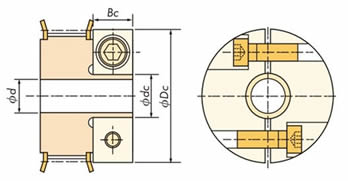
| dc mm |
Dc mm |
Bc mm |
Number | Size | Tightening torque M.A. |
Transmission Torque Mt |
Thrust load Pax |
Shaft side pressure P |
Transmission Torque Mt |
Thrust load Pax |
Shaft side pressure P |
||||||||||
| N・m | kgf・m | N・m | kgf・m | N・m | kgf・m | N・m | kgf・m | N・m | kgf・m | N・m | kgf・m | N・m | kgf・m | ||||||||
| C1 | 9.2 | 30 | 10 | 19 | 2 | M4×12 | 3.8 | 0.39 | 6 | 2.8 | 0.29 | 0.93 | 95 | 193 | 19.7 | 6.9 | 0.70 | 0.7 | 72 | 266 | 27.1 |
| 7 | 3.5 | 0.36 | 1.00 | 102 | 185 | 18.9 | 7.1 | 0.72 | 0.75 | 77 | 255 | 26.0 | |||||||||
| C2 | 11.0 | 33 | 10 | 22 | M4×12 | 3.8 | 0.39 | 8 | 4.7 | 0.48 | 1.18 | 120 | 162 | 16.5 | 9.2 | 0.94 | 1.11 | 114 | 223 | 22.8 | |
| 9 | 4.9 | 0.5 | 1.09 | 111 | 144 | 14.7 | 9.9 | 1.01 | 1.35 | 138 | 198 | 20.2 | |||||||||
| C3 | 13.4 | 40 | 12 | 39 | M5×15 | 7.5 | 0.77 | 10 | 11.1 | 1.13 | 2.22 | 227 | 151 | 15.4 | 18.9 | 1.93 | 2.45 | 250 | 208 | 21.2 | |
| 11 | 8.9 | 0.91 | 1.62 | 165 | 150 | 15.3 | 17.9 | 1.83 | 2.34 | 239 | 207 | 21.1 | |||||||||
| C4 | 16.4 | 42 | 12 | 42 | M5×20 | 7.5 | 0.77 | 12 | 13.4 | 1.37 | 2.23 | 228 | 138 | 14.1 | 22.7 | 2.32 | 3.22 | 329 | 190 | 19.4 | |
| 14 | 14.2 | 1.45 | 2.03 | 207 | 118 | 12.0 | 26.4 | 2.69 | 4.39 | 447 | 163 | 16.6 | |||||||||
| C5 | 19.4 | 45 | 12 | 46 | M5×20 | 7.5 | 0.77 | 15 | 19.1 | 1.95 | 2.55 | 260 | 110 | 11.2 | 28.3 | 2.89 | 5.04 | 515 | 152 | 15.5 | |
| 16 | 22.9 | 2.34 | 2.86 | 292 | 103 | 10.5 | 30.2 | 3.08 | 5.75 | 586 | 142 | 14.5 | |||||||||
| 17 | 19.7 | 2.01 | 2.32 | 236 | 97 | 9.9 | 32.1 | 3.28 | 6.49 | 662 | 134 | 13.7 | |||||||||
| C6 | 22.8 | 53 | 15 | 78 | M6×20 | 12.6 | 1.3 | 18 | 35.7 | 3.64 | 3.97 | 405 | 98 | 100 | 47.8 | 4.88 | 9.56 | 976 | 134 | 13.7 | |
| 19 | 38.4 | 3.92 | 4.04 | 412 | 100 | 10.2 | 50.5 | 5.15 | 9.9 | 1010 | 137 | 14.0 | |||||||||
| 20 | 31.9 | 3.26 | 3.19 | 326 | 95 | 9.7 | 53.2 | 5.43 | 10.98 | 1120 | 131 | 13.4 | |||||||||
Approximate mass
The approximate mass is the mass of Standard Stock Belt Sprockets plus the mass of the clamp collar in the table above.

